Display apparatus

Active Publication Date: 2005-05-19
SHARP KK
View PDF3 Cites 40 Cited by
  • Summary
  • Abstract
  • Description
  • Claims
  • Application Information

AI Technical Summary

Benefits of technology

[0047] The method adjusts a control signal for the lamp according to a change in display brightness in a bright scene. In a dark scene, a conventional control signal is used to improve black contrast. In this way, white peak can be improved in a bright scene without causing pale black display in a dark scene.
[0048] Further, the method can provide a wider dynamic range than the conventional method, because the minimum luminance that can be displayed in the display apparatus is equal to the minimum luminance of the conventional method when the white peak luminance is not improved, and because the maximum luminance that can be displayed in the display apparatus is equal to the maximum luminance of the conventional method when the white peak luminance is improved.
[0049] In improving white peak luminance, the conventional method turns on the lamp above a normal brightness so that the peak luminance is improved throughout a bright scene. In contrast, in the present embodiment, the brightness of the lamp is merely increased spontaneously when the peak level of the video signal increases, thereby reducing power consumption than conventionally in improving white peak.
[0050] In the display apparatus of the present invention, the varied component detecting block includes: a level converting circuit for subtracting a predetermined threshold from the optical output level extension signal outputted from the optical output control means, so as to output a positive component of a subtraction result; a differentiating circuit for differentiating an output signal of the level converting circuit with a certain time constant; a luminance ad

Problems solved by technology

However, a problem of this conventional method whereby white peak luminance is improved, for example, by uniformly extending the control signal for the backlight is that the output video appears brighter than the input video in a dark scene, as compared with setting the maximum luminance at normal level.
Another drawback of the foregoing method is that the extension of

Method used


Image

  • Display apparatus
  • Display apparatus
  • Display apparatus

Examples


first embodiment

[First Embodiment]

[0076] One embodiment of the present invention is described below referring to FIG. 1 through FIG. 10. It should be noted that the present embodiment describes a liquid crystal display device as one form of a display apparatus. The liquid crystal display device may be a liquid crystal display panel, or other types of displays such as a projection-type liquid crystal projector.

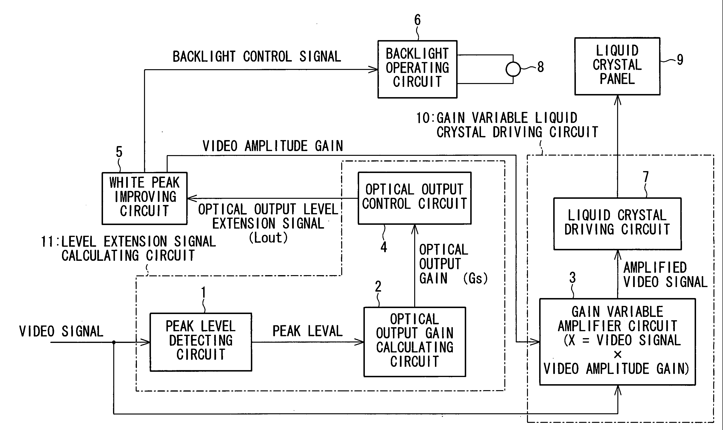
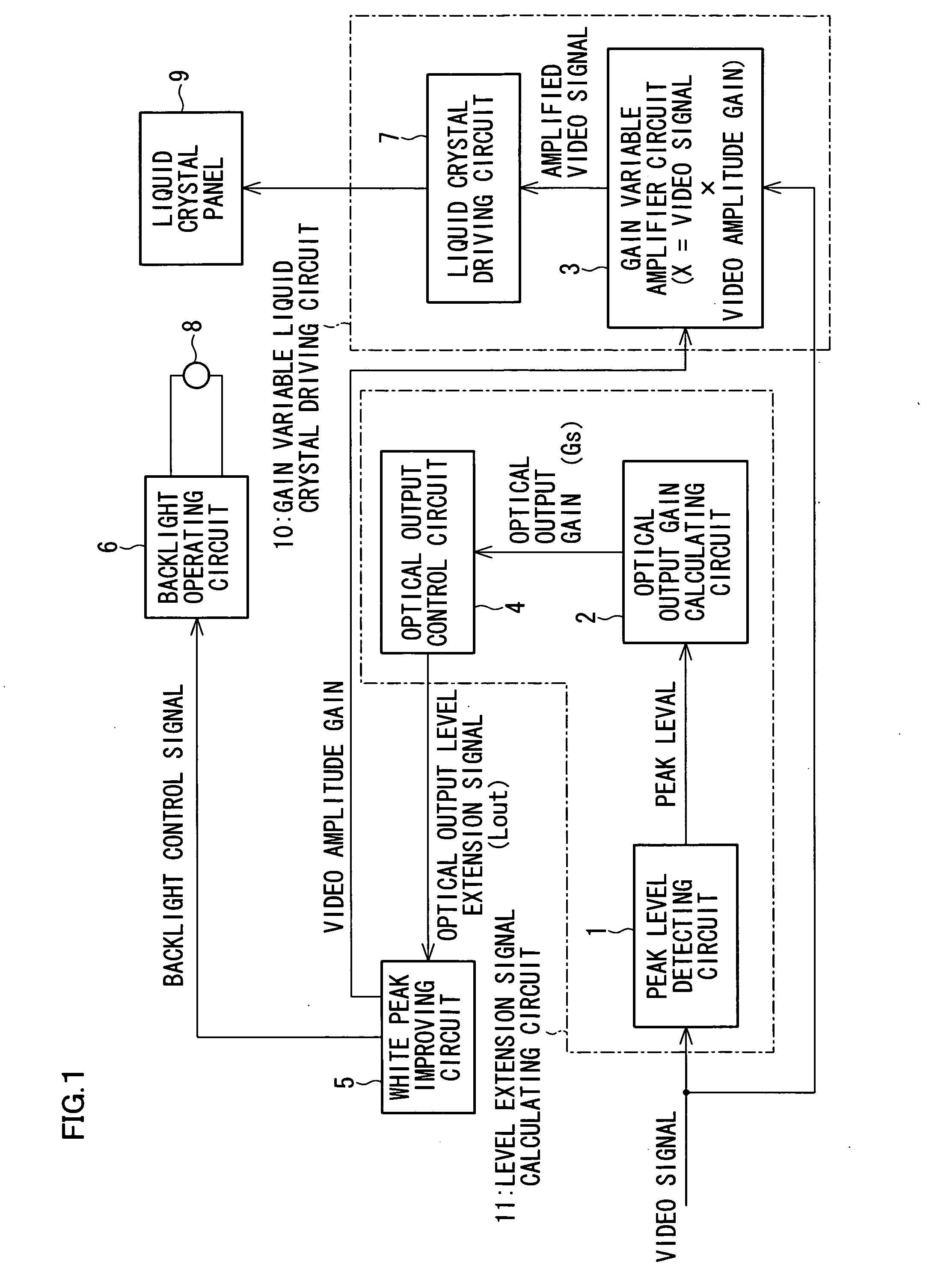
[0077] As illustrated in FIG. 1, the liquid crystal display device of the present embodiment includes: a liquid crystal panel 9 provided as a display panel; a gain variable liquid crystal driving circuit 10 provided as coefficient variable driving means; a backlight operating circuit 6 provided as operating means for operating a backlight 8 (provided as a lamp for illuminating the liquid crystal panel 9) based on a backlight control signal (lamp control circuit); a level extension signal calculating circuit 11 provided as extension signal calculating means; and a white peak improving circuit ...

second embodiment

[Second Embodiment]

[0144] The following will describe another embodiment of the present invention with reference to FIG. 11 and FIG. 12. Note that, for convenience of explanation, constituting elements having the same functions as those described in the First Embodiment are given the same reference numerals and further explanations thereof are omitted here.

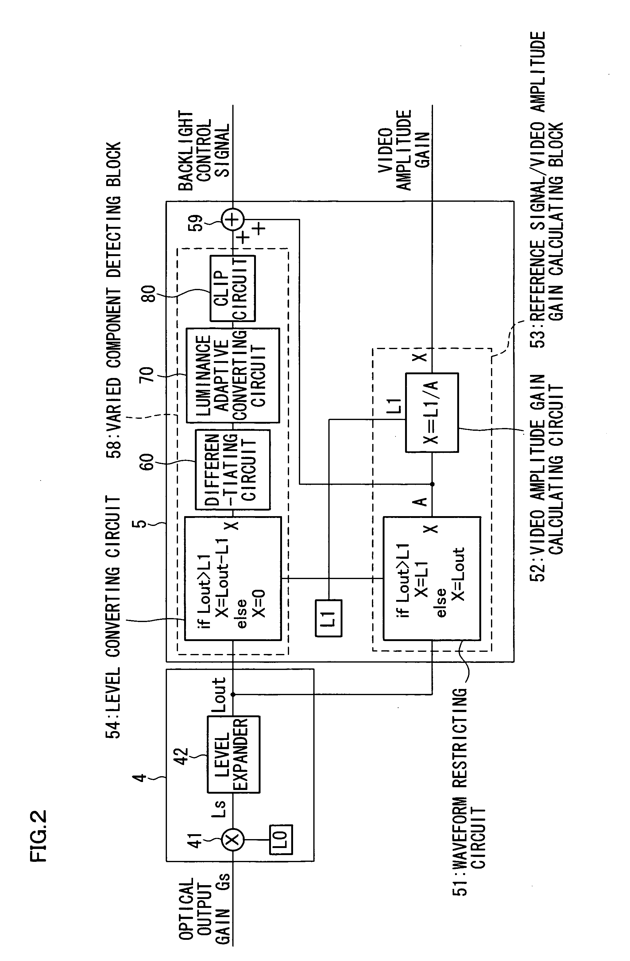
[0145] For the overall structure of a liquid crystal display device according to the present embodiment, FIG. 1 of the First Embodiment should be referred to. However, the liquid crystal display device of the present embodiment differs from that of the First Embodiment in the operations of the optical output control circuit 4 and the white peak improving circuit 5. Namely, the luminance adaptive converting circuit 70 of the First Embodiment shown in FIG. 6 sets a coefficient αm=0 so as not to facilitate a change in brightness in the negative direction. Likewise, a change in brightness in the negative direction is not facilitated ...


PUM


Abstract

The invention provides a display panel 9; a gain variable liquid crystal driving circuit 10 for driving the display panel 9 with an amplified video signal that is obtained by multiplying an input video signal by a variable coefficient; a backlight operating circuit 6 for operating, based on a lamp control signal, a backlight 8 for illuminating the display panel 9; a level extension signal calculating circuit 11 for outputting an optical output level extension signal Lout by extending a predetermined output level used to operate the backlight 8, wherein the predetermined output level is extended based on an optical output gain obtained from the input video signal, and an output peak value of the backlight 8; and a white peak improving circuit 5 for receiving the optical output level extension signal, and for outputting a lamp control signal, whose white peak level has been adjusted according to a change in brightness of a scene, to the backlight operating circuit 6, and for calculating and outputting a video amplitude gain, which adjusts an amplitude of a video signal, as a coefficient to a gain variable driving amplifier circuit 3, wherein the lamp control signal is outputted when the brightness of a scene is above normal level, and the video amplitude gain is outputted when the brightness is at normal level. As a result, there is provided a display apparatus that improves peak luminance in a bright scene and suppresses pale black display in a dark scene and thereby provide a wide dynamic range without increasing power consumption.

Description

TECHNICAL FIELD [0001] The present invention concerns improvement in display quality of a display panel such as a liquid crystal panel, and particularly relates to a display apparatus for improving both contrast in a dark scene and white peak luminance. BACKGROUND ART [0002] In recent years, various types of liquid crystal color displays have been developed and marketed. One of the important goals in achieving better display quality in liquid crystal displays is to improve white peak in a bright scene and contrast in a dark scene. [0003] In one conventional method of improving contrast in a dark scene, a gain is calculated from the peak level of a video signal during predetermined intervals of time, and the output level of light is reduced and the amplitude of the video signal is extended according to the calculated gain, as disclosed in Japanese Unexamined Patent Application Nos. 102484 / 1994 (Tokukaihei 6-102484; published on Apr. 15, 1994), 109317 / 1999 (Tokukaihei 11-109317; publi...

Claims


Application Information

Patent Timeline
IPC IPC(8): G09G3/20G09G3/34G09G3/36
CPCG09G3/2011G09G3/2077G09G3/3406G09G3/3611G09G2360/16G09G2320/0633G09G2320/0646G09G2320/066G09G2330/021G09G2320/0626G02F1/133
Inventor SASAKI, TAKASHI
Owner SHARP KK
Why Eureka
Try Eureka