
Fluorometer

a fluorometer and fluorescence technology, applied in the field of fluorometers, can solve the problems of detector blindness, no time-resolved fluorometry, photometry, luminometry, etc., and achieve the effect of easy omission or addition

Inactive Publication Date: 2005-05-19
BECKMAN COULTER INC
View PDF21 Cites 35 Cited by
  • Summary
  • Abstract
  • Description
  • Claims
  • Application Information

AI Technical Summary

Benefits of technology

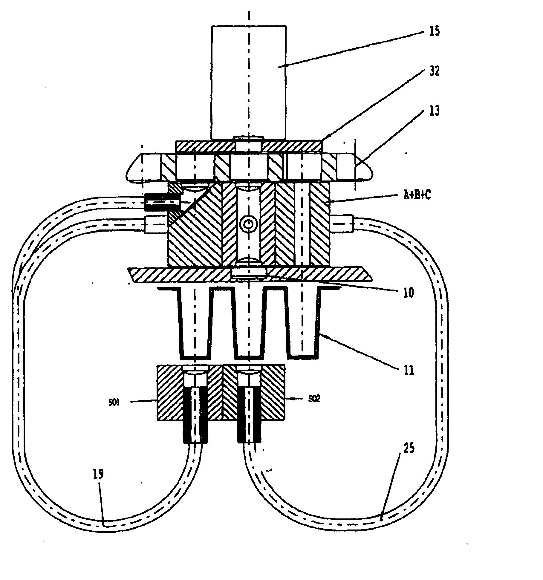
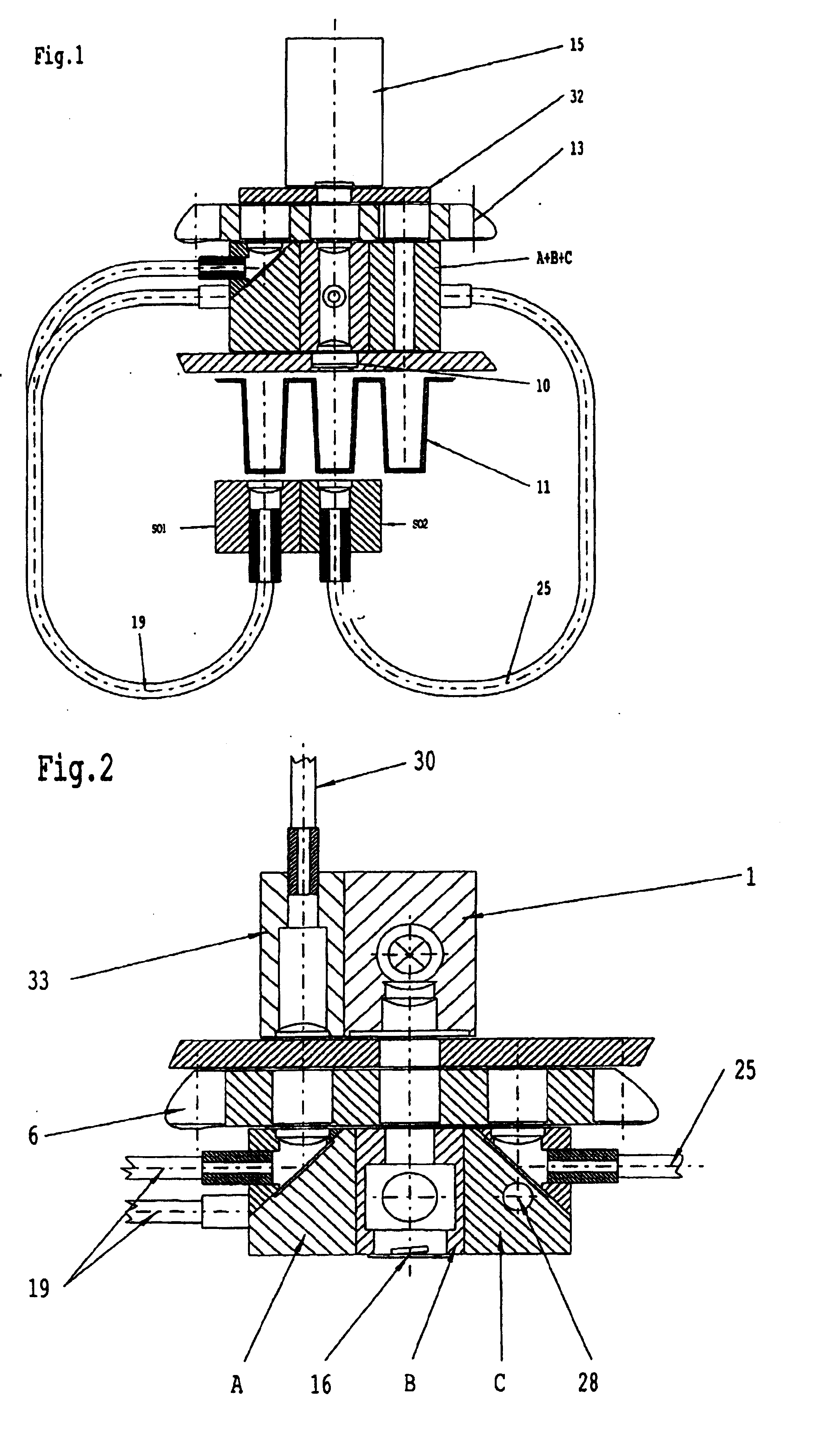
The invention is a fluorometer that can be easily adapted to different requirements by using a measuring head made up of multiple optical blocks that can be assembled in a modular way. Each optical block can perform a different measurement method using the common detector. This modular design allows for easy addition or omission of parts needed for fluorometry, with only the base unit requiring the necessary parts for fluorometry read from above. All other parts can be added in a modular manner as required.

Problems solved by technology

No time-resolved fluorometry, photometry, luminometry or polarization fluorometry can be measured with this apparatus.
The detector is blinded if the flash energy is too intense as the photosensitive layer of the detector is damaged.

Method used


Image

  • Fluorometer
  • Fluorometer
  • Fluorometer

Examples


Embodiment Construction

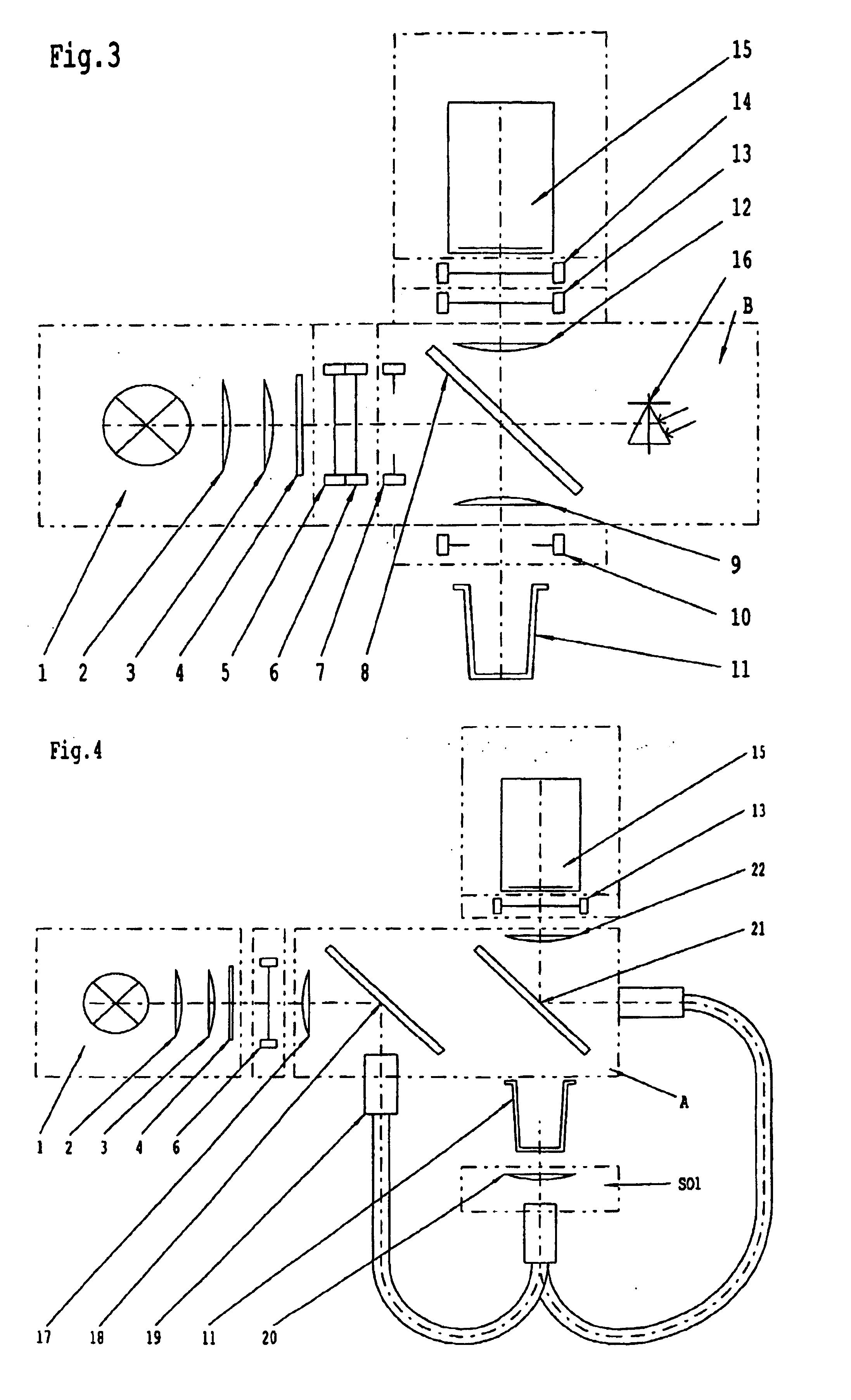
[0018] The basic equipment for all measurement methods consists of a detector 15 in the form of a photomultiplier PMT, optical block (B), first and second filter slides 6, 13 and a light source 1. Optical block B is used for fluorometry measured from above, i.e. for top-reading fluorometry and for time-delayed fluorometry (time-resolved fluorometry). A first light source 1 (FIG. 3, 4) consists of a halogen lamp with six volts and 20 watts without UV stop, two lenses 2, 3 made of non-fluorescent quartz glass, and a heat-protection glass 4 for the suppression of parasitic infrared radiation in a self-contained lamp block. The first light source 1 is used for fluorescence measurement from above and from below and for photometry. The first light source 1 is rigidly connected to a light guide holder 33 for a second light source 29 (FIG. 5) which preferably is formed by a xenon flashlamp and has a motor drive. The light source 1 and the light guide holder 33 can thus be changed automatica...


PUM

PropertyMeasurementUnit
angleaaaaaaaaaa
distanceaaaaaaaaaa
distanceaaaaaaaaaa

Abstract

A fluorometer with at least one light source, a measuring station with a holder for at least one specimen, a measuring head, and an evaluation station with a detector for evaluating emission signals emitted by a specimen. The measuring head is formed by three optical blocks (A, B, C) assembled in a modular manner. A different measurement method is able to be carried out with each optical block (A, B, C). All the optical blocks (A, B, C) operate the same detector.

Description

CROSS REFERENCE TO RELATED APPLICATIONS [0001] The present invention claims priority of PCT Application No. PCT / AT02 / 00157 filed on May 23, 2002, which claims priority of Austrian Patent Application No. A818 / 2001, filed on May 23, 2001, the entire contents of which are hereby incorporated herein by reference. BACKGROUND OF THE INVENTION [0002] The invention relates to a fluorometer with at least one light source, a measuring station with a receptacle for at least one specimen container, in particular for receiving microplates and polymerase chain reaction tubes (PCR tubes), a measuring head, as well as an evaluation station with a detector, preferably a photomultiplier (PMT), for evaluating the emission signals emitted by a specimen. [0003] A compact fluorometer measuring head module is known from U.S. Pat. No. 6,084,680 which can be used only for one measurement method (without modification). No time-resolved fluorometry, photometry, luminometry or polarization fluorometry can be m...

Claims


Application Information

Patent Timeline
Patent Type & Authority Applications(United States)
IPC IPC(8): G01N21/25G01N21/64
CPCG01N21/6445G01N21/6452G01N2201/024G01N2021/6471G01N2021/6484G01N2021/6463
Inventor LANDLINGER, RICHARD
Owner BECKMAN COULTER INC
Learn More