Method of measuring thermal conductivity of honeycomb structure

Active Publication Date: 2005-05-19
NGK INSULATORS LTD
View PDF28 Cites 16 Cited by
  • Summary
  • Abstract
  • Description
  • Claims
  • Application Information

AI Technical Summary

Benefits of technology

[0016] [4] The method for measurement of thermal conductivity of a honeycomb structure set forth in the above [2] or [3], wherein the two ends of the honeycomb structure and the contact members are contacted with each other via high-thermal-conductivity members.
[0017] [5] The method for measurement of thermal conductivity of a honeycomb structure set forth in the above [4], wherein a sheet havin

Problems solved by technology

However, since the honeycomb structure has a special construction, there has heretofore been established no method for measuring the thermal conductivity of the honeycomb structure per se without preparing a test spec

Method used


Image

  • Method of measuring thermal conductivity of honeycomb structure
  • Method of measuring thermal conductivity of honeycomb structure

Examples


examples

[0051] The present invention is described more specifically by way of Examples. However, the present invention is not restricted to these Examples.

examples 1 to 7

[0052] There were produced, by ordinary extrusion molding, two kinds of honeycomb structures made of metallic silicon-bonded silicon carbide (silicon carbide bonded with metallic silicon) and having a rib thickness of 15 mil and a cell density of 200 cpsi (cells per square inch) or 300 cpsi.

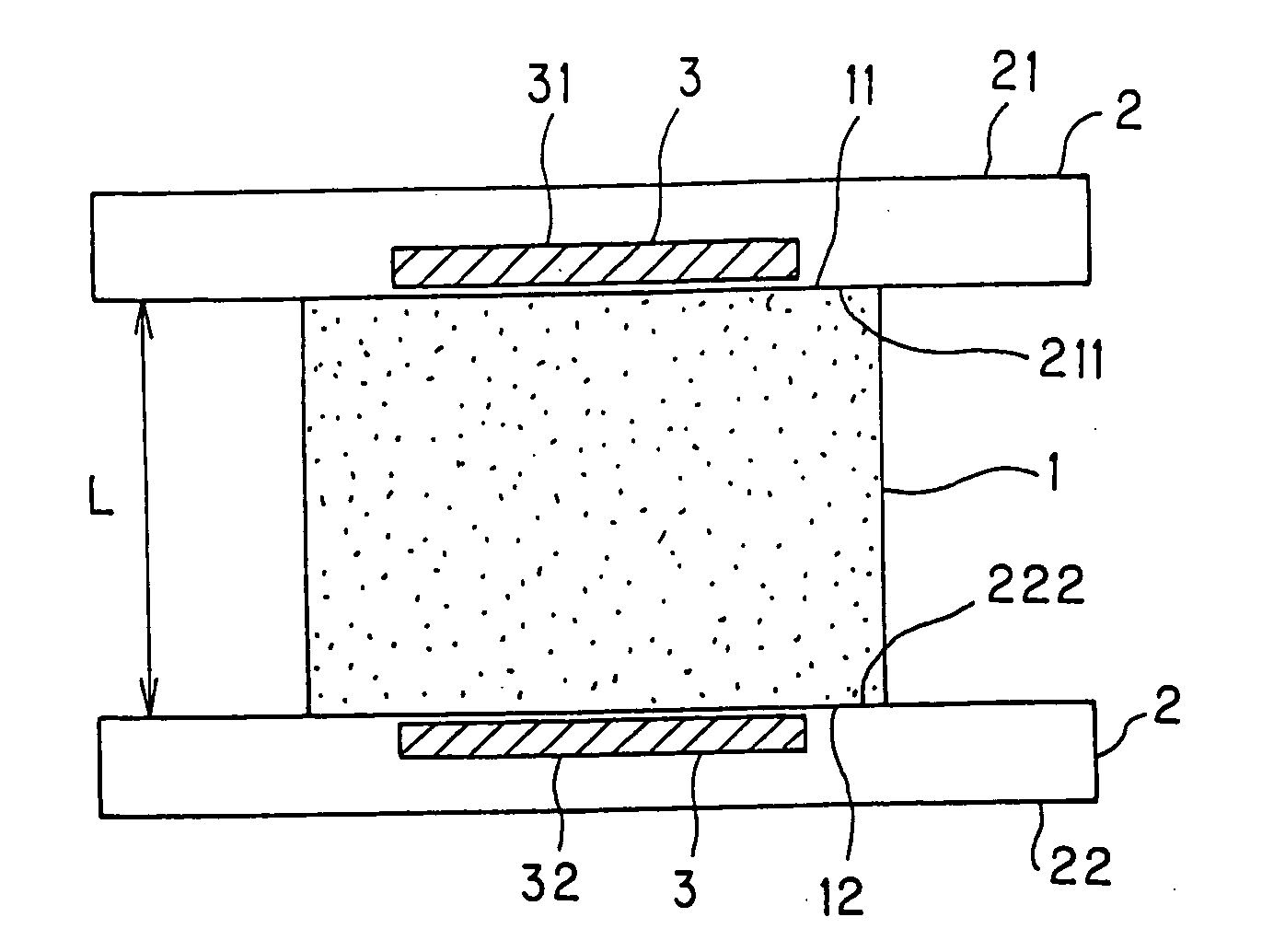
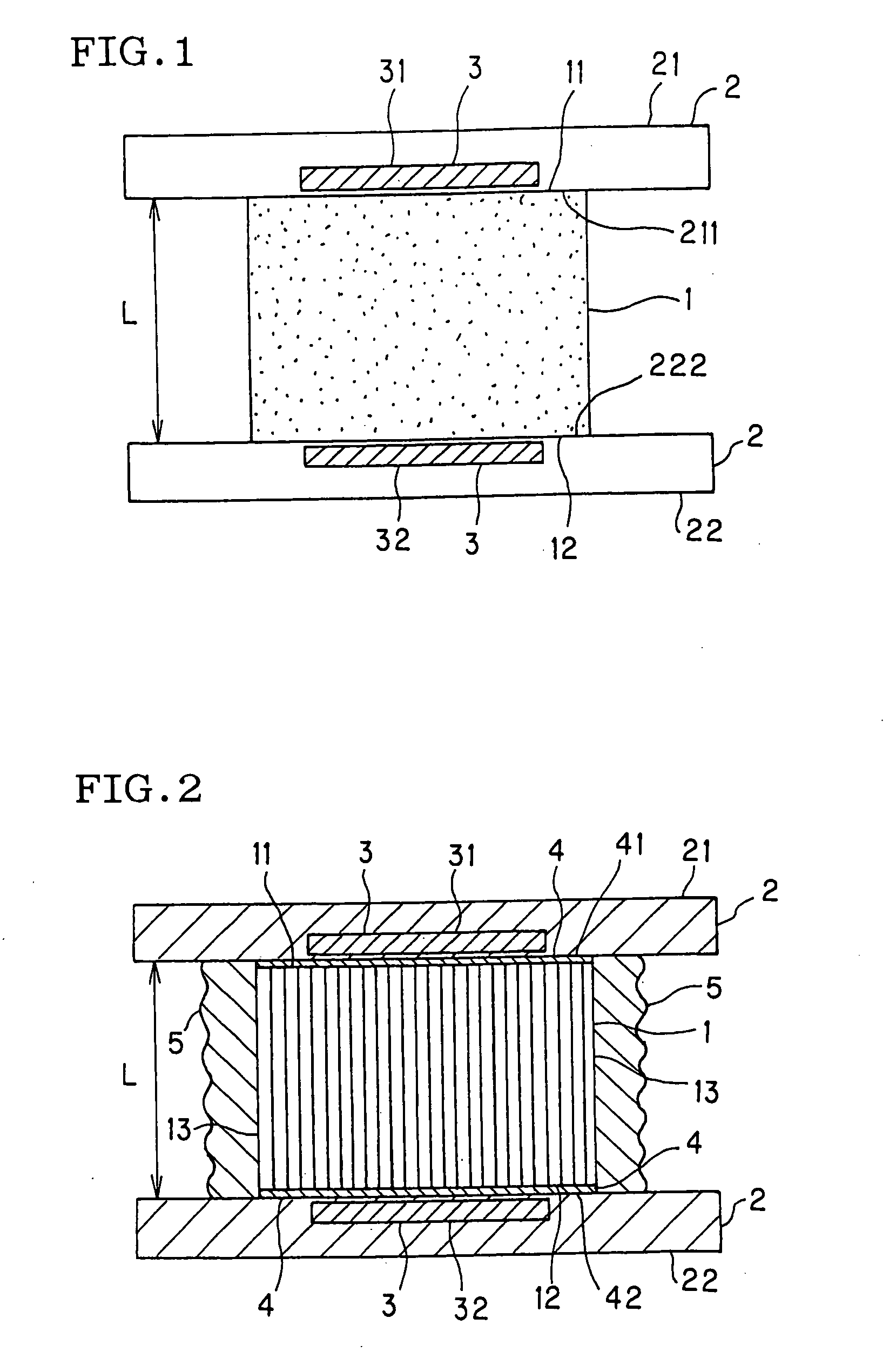
[0053] A block of 35 mm×35 mm×25 mm was cut out from each of the two kinds of honeycomb structures and measured for thermal conductivity by a steady method, using neither high-thermal-conductivity member nor heat-insulating material, as shown in FIG. 1. Each block was measured for thermal conductivity by the steady method using both or either of high-thermal-conductivity members and a heat-insulating material, as shown in FIG. 2. The results are shown in Table 1.

TABLE 1Example 1Example 2Example 3Example 4Example 5Example 6Example 7High-thermal-conductivity memberNot usedCarbon sheetNot usedAluminumCarbon sheetNot usedCarbonfoilsheetHeat-insulating materialNot usedNot usedPolystyreneNot usedPol...


PUM


Abstract

The method for measurement of thermal conductivity of a honeycomb structure according to the present invention comprises the steps keeping the whole honeycomb structure in a steady temperature state with keeping two ends of the honeycomb structure at given different temperatures; and measuring a thermal conductivity of the honeycomb structure in the steady state. According to the present invention there is provided a method for measurement of thermal conductivity of a honeycomb structure, which can measure the thermal conductivity of a honeycomb structure in the shape of the honeycomb structure per se or in a predetermined block shape without preparing, for example, a test specimen of particular shape.

Description

TECHNICAL FIELD [0001] The present invention relates to a method for measurement of thermal conductivity of a honeycomb structure, which can measure the thermal conductivity of a honeycomb structure in the shape of the honeycomb structure per se without preparing a test specimen or the like. BACKGROUND ART [0002] Honeycomb structures (honeycomb filters) made of a ceramic are in use in order to capture the dust or another particulate matter contained in, for example, the exhaust gas emitted from automobiles (particularly, diesel engine automobiles) or the incineration gas generating during the incineration of waste, or to recover a product or a raw material from the high-temperature waste gas emitted in production processes of various industries. These honeycomb structures have a large number of through-holes surrounded by partition walls and extending in the axial direction of a honeycomb structure; the partition walls surrounding the through-holes have a filtration ability; a given...

Claims


Application Information

Patent Timeline
IPC IPC(8): G01N25/18
CPCG01N25/18
Inventor ICHIKAWA, SHUICHIOTSUKA, AIKOITOU, MOTOMICHIMAKINO, TAKUMA
Owner NGK INSULATORS LTD
Why Eureka
Try Eureka