
Spatial scalable compression scheme using spatial sharpness enhancement techniques

a spatial sharpness enhancement and compression scheme technology, applied in the field of video encoder/decoder, can solve the problems of large amounts of raw digital information included large amount of raw digital information in high-resolution video sequences, and large amount of raw digital information in reconstructed streams, so as to achieve the effect of increasing the video compression of a scalable compression schem

Inactive Publication Date: 2005-05-19
KONINKLIJKE PHILIPS ELECTRONICS NV
View PDF1 Cites 24 Cited by
  • Summary
  • Abstract
  • Description
  • Claims
  • Application Information

AI Technical Summary

Benefits of technology

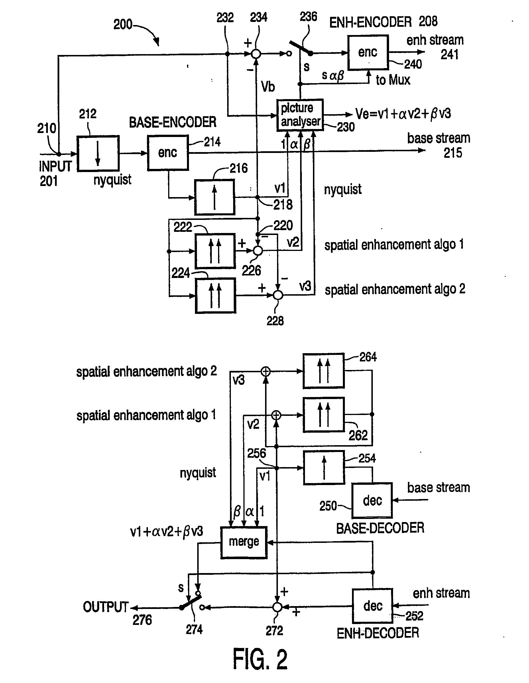
[0010] According to another embodiment of the invention, a mix of the enhanced base video streams and the decoded upscaled base bitstream can be used to control the information in the encoded residual bitstream, i.e., which pixels or groups of pixels should be included in the decoded residual bitstream.
[0011] These and other aspects of the invention will be apparent from and elucidated with reference to the embodiments described hereafter.

Problems solved by technology

Because of the massive amounts of data inherent in digital video, the transmission of full-motion, high-definition digital video signals is a significant problem in the development of high-definition television.
As a result, the amounts of raw digital information included in high-resolution video sequences are massive.
However, because of the filtering and the losses resulting from the encoding and decoding, certain errors are present in the reconstructed stream.
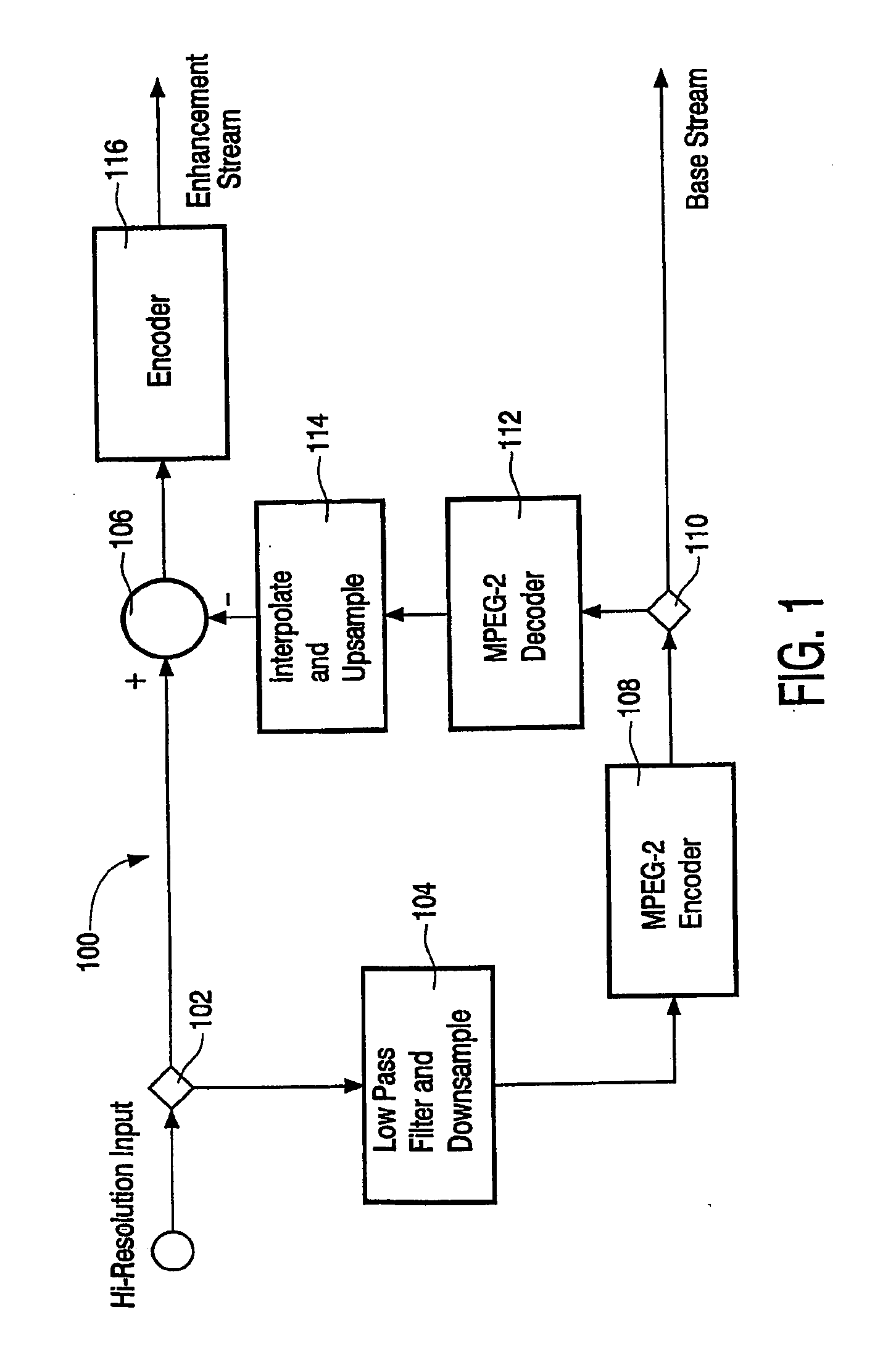
The disadvantage of filtering and downscaling the input video to a lower resolution and then compressing it is that the video loses sharpness.
Although this can be made to work reasonably well for most parts of the video picture, there are some areas within the picture where the result remains poor compared to the original picture, e.g., small text parts will remain unreadable even with the most sophisticated enhancement.

Method used


Image

  • Spatial scalable compression scheme using spatial sharpness enhancement techniques
  • Spatial scalable compression scheme using spatial sharpness enhancement techniques
  • Spatial scalable compression scheme using spatial sharpness enhancement techniques

Examples


Embodiment Construction

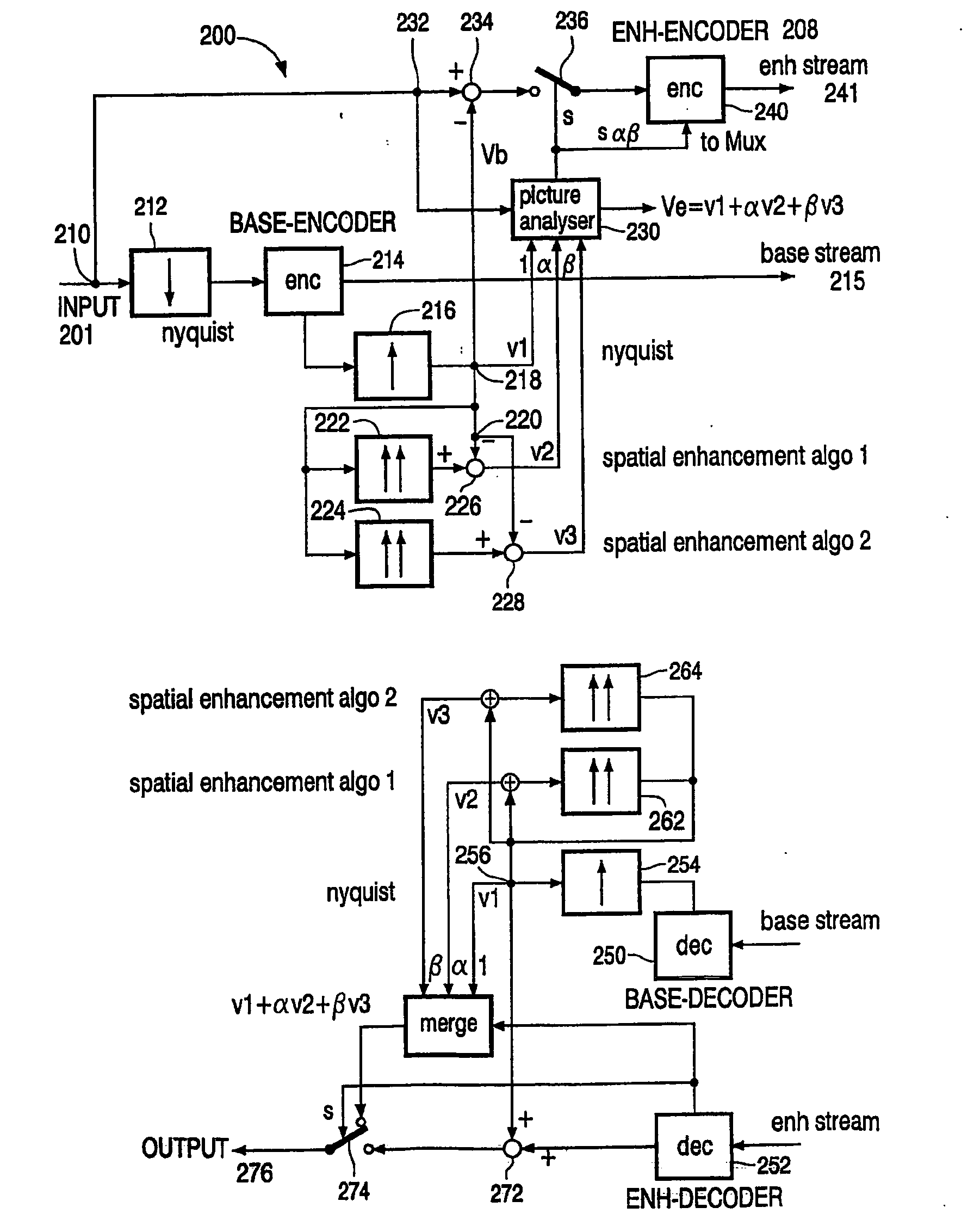
[0017] According to one embodiment of the invention, a spatial scalable compression scheme using spatial sharpness enhancement techniques is disclosed. Briefly, the filtered and downscaled video sequence is compressed. Then, out of the decoded base layer frames, several upscaled versions are processed using a variety of enhancement algorithms. This can include a standard upscaled and filtered, for example, nyquist filtered, versions as well as various sharpness enhancement algorithm versions. A picture analyzer processes all of the information and selects the best or the best mix of these versions. The mix parameters which define the selected mix is also inserted in the encoded residual bitstream, as user data, so that the decoder can exactly reproduce this enhancement.

[0018] However, in some areas of the sharpness enhanced frames, the results will remain inadequate. By comparing in the encoder the available original full resolution frames with the enhancement frames, these areas c...


PUM


Abstract

A video encoder / decoder with spatial scalable compression schemes using spatial sharpness enhancement techniques is disclosed. The video compression scheme introduces a number of various video enhancement techniques on the base layer. A picture analyzer is used to determine the best or the best mix of various video enhancement techniques. The picture analyzer compares the selected mix of video enhancement techniques with the original full resolution input signal to determine for which of the pixels or groups of pixels a residual enhancement layer is required. Parameters defining the selected mix of video enhancement techniques are transmitted to the decoder layer so the same mix of video enhancement techniques can be used in the decoder layer.

Description

FIELD OF THE INVENTION [0001] The invention relates to a video encoder / decoder, and more particularly to a video encoder / decoder with spatial scalable compression schemes using spatial sharpness enhancement techniques. BACKGROUND OF THE INVENTION [0002] Because of the massive amounts of data inherent in digital video, the transmission of full-motion, high-definition digital video signals is a significant problem in the development of high-definition television. More particularly, each digital image frame is a still image formed from an array of pixels according to the display resolution of a particular system. As a result, the amounts of raw digital information included in high-resolution video sequences are massive. In order to reduce the amount of data that must be sent, compression schemes are used to compress the data. Various video compression standards or processes have been established, including, MPEG-2, MPEG-4, and H.263. [0003] Many applications are enabled where video is ...

Claims


Application Information

Patent Timeline
Patent Type & Authority Applications(United States)
IPC IPC(8): H04N7/26H04N7/30H04N7/46H04N7/50
CPCH04N19/147H04N19/172H04N19/115H04N19/61H04N19/12H04N19/124H04N19/577H04N19/182H04N19/187H04N19/192H04N19/33H04N19/517H04N19/587H04N19/132
Inventor BRULS, WILHELMUS HENDRIKUS ALFONSUSDE BRUIJN, FREDERIK JANDANTWALA, NEHAL R.
Owner KONINKLIJKE PHILIPS ELECTRONICS NV
Learn More