
Alternator fan

Inactive Publication Date: 2005-05-19
VALEO EQUIP ELECTRIC MOTEUR
View PDF3 Cites 22 Cited by
  • Summary
  • Abstract
  • Description
  • Claims
  • Application Information

AI Technical Summary

Benefits of technology

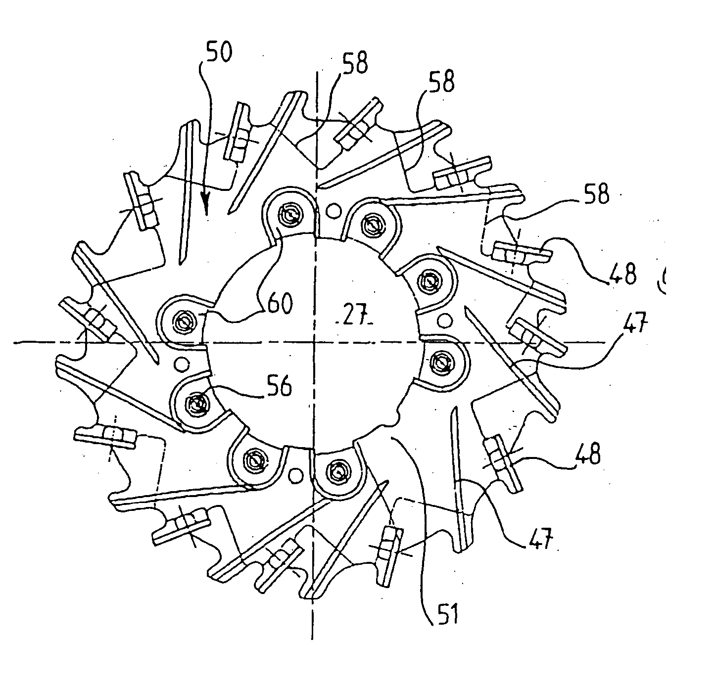
[0007] The moulded-on fan thus has enhanced mechanical strength because of the insert, which is preferably made of metal and which comprises at least a portion of a blade and consolidates the plastics part of the fan. Similarly the cost of the moulded fan is reduced because the insert, since it comprises at least a portion of a blade, occupies a relatively large space and ensures good mechanical strength, so that the quantity of plastics material which is necessary for the manufacture of the moulded fan is reduced. In addition, the insert determines the form and disposition, and the required number of blades are those desired. The blades may be very close to each other or of complex form, while being robust because the insert carries at least part of a blade of the fan, which enables better anchorage of the plastics material on the insert, and therefore greater homogeneity in the fan, to be obtained. The fan is thus able to rotate at high speeds, to be of high power, and to be less noisy and mounted in a motor vehicle alternator.
[0010] Thus, good mechanical strength of the fan is ensured with a reduced amount of plastics material, the volume of the wheel part being essentially occupied by the insert.
[0012] Thus, the mechanical strength of the circumferential end of the fan is ensured because this part of the fan, not being moulded in situ, remains very close to the end of the insert, which greatly reduces the mechanical stresses applied on this external part of the fan while it is working in rotation.
[0028] The metallic insert has at least one opening for increasing the mechanical strength of the in situ moulding.

Problems solved by technology

These fans may be used in alternators of high electrical output, which are liable to produce excessive heating when ventilation is poor.
However, these known fans have the major disadvantages that their manufacture is costly because of the large quantity of plastics material which is necessary, and which is expensive, and also because their mechanical strength is poor, again due to the high mass of plastics material which is used.

Method used


Image

  • Alternator fan
  • Alternator fan
  • Alternator fan

Examples


Embodiment Construction

OF PREFERRED EMBODIMENTS OF THE INVENTION

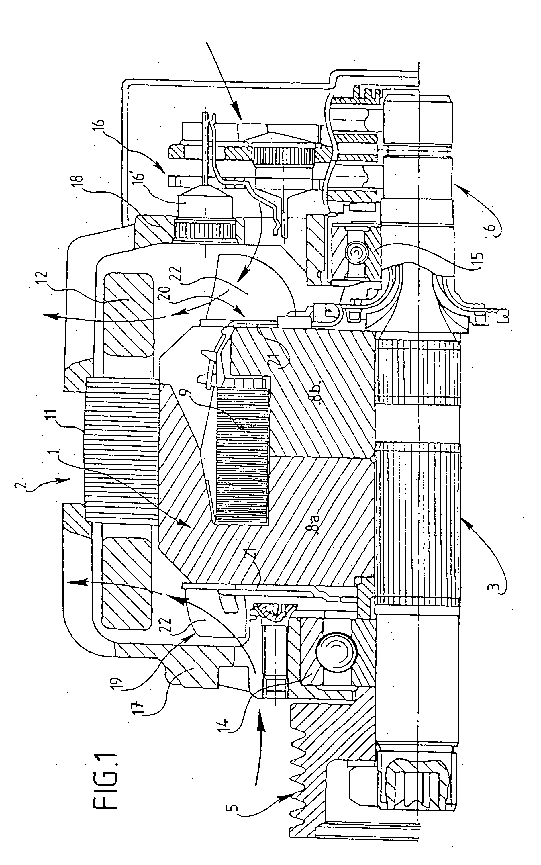
[0043] The sole purpose of FIG. 1 is to recall briefly the general structure of a polyphase alternator with internal ventilation for a motor vehicle heat engine, with a view to putting the invention in its preferred practical context. For an understanding of the invention, it is sufficient to mention that the alternator shown comprises essentially a rotor 1 surrounded by a stator 2 and mounted on a rotor shaft 3 for rotation with the latter, the front end of the rotor shaft carrying in rotation a drive pulley 5, while its rear end carries slip rings (not given a reference numeral) of a collector 6. The pulley 3 is arranged to be coupled to the heat engine of the vehicle in the known way, through a belt drive.

[0044] In this example the rotor is of the claw type and comprises two pole wheels designated by the references 8a and 8b, which have axially oriented teeth offset angularly as between one wheel and the other. The reference numeral 9 des...


PUM


Abstract

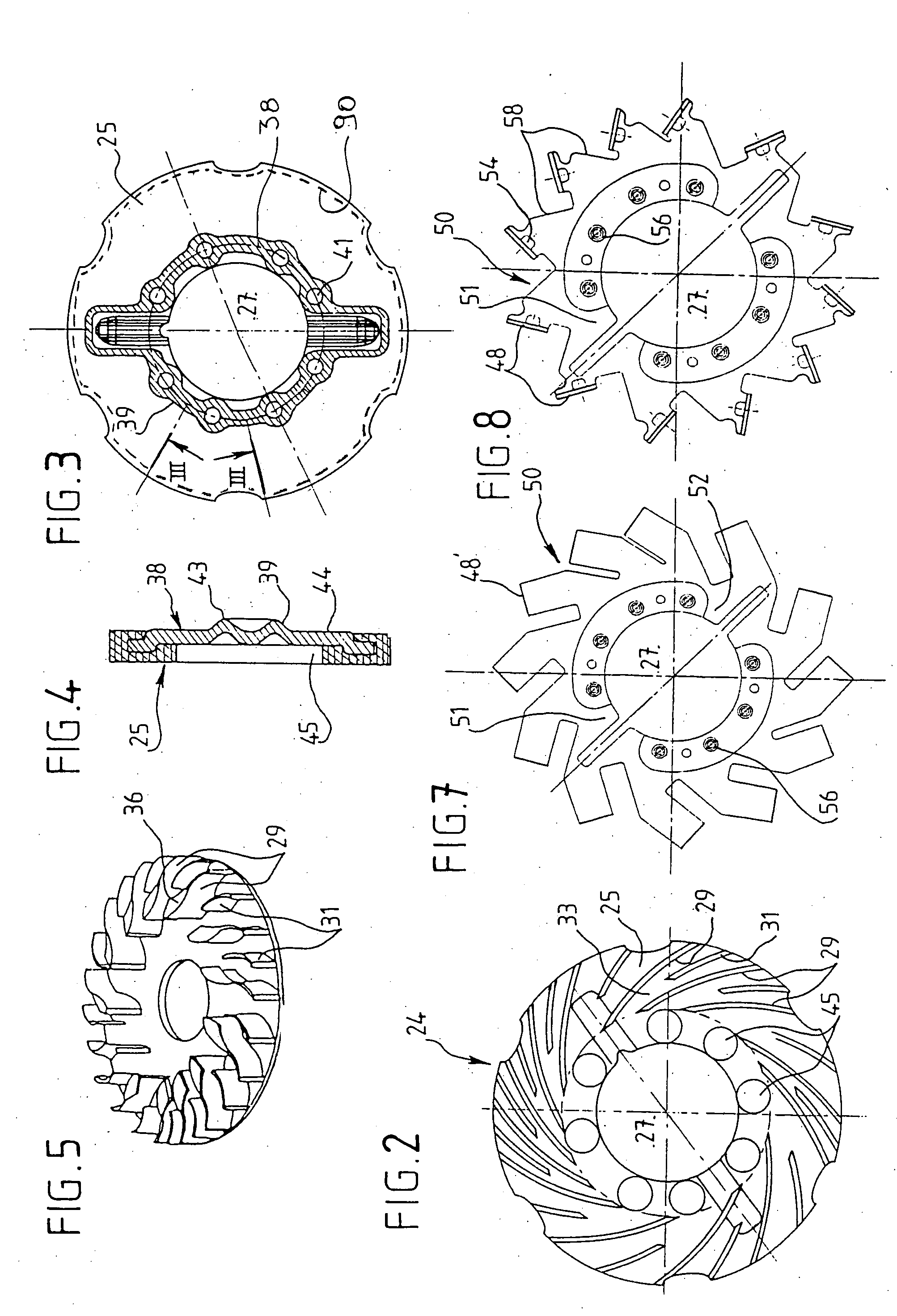
The invention is a fan for an alternator adapted to be coupled in rotation to the alternator rotor, and being of the type comprising a wheel part and a plurality of fan blades (47, 48) extending from the latter, the fan being moulded in a plastics material on an insert (50) which is preferably of metal and which constitutes the wheel part of the fan and is arranged to provide fastening of the fan on the rotor, being configured so as to constitute a means for increasing the mechanical strenght of the fan; the insert (50, 65) includes at least a portion of a blade (48, 69) of the fan. The invention is useful in the manufacture of a high power cooling fan for a motor vehicle alternator.

Description

FIELD OF THE INVENTION [0001] This invention relates to a fan for an alternator, especially for a motor vehicle. The fan is adapted to be coupled in rotation to the rotor of the alternator, and comprises a wheel part and a plurality of fan blades extending from the latter; the fan is formed by moulding in a plastics material on a mechanical insert, in a material which is mechanically stronger than the plastics material, such as metal, and the insert constitutes the part of the fan by which it is secured on the support. STATE OF THE ART [0002] Fans of this type are already known and are described for example in the Applicant's French patent No. 2 673 338. In the fan described in that patent, the insert is of metal and is disposed in the wheel part, and serves for fastening of the fans to the rotor, in particular by welding. Given that the fan of plastics material is moulded on the insert with its fan blades, it is possible to make fans which have blades the number, configuration and ...

Claims


Application Information

Patent Timeline
IPC IPC(8): F04D29/02F04D29/28
CPCF04D29/282F04D29/023F05D2300/43F05D2230/232H02K9/06
Inventor VASILESCU, CLAUDIUARRIGHI, SEBASTIEN
Owner VALEO EQUIP ELECTRIC MOTEUR
Learn More