Designed particle agglomeration

a technology of agglomeration and particles, applied in the field of agglomeration of particles, can solve the problems of complex structure, unstable dispersions of fine particles, and difficulty in processing,

Inactive Publication Date: 2005-05-19
EI DU PONT DE NEMOURS & CO
View PDF9 Cites 16 Cited by
  • Summary
  • Abstract
  • Description
  • Claims
  • Application Information

AI Technical Summary

Benefits of technology

[0011] c) forming particle agglomerates having a desired size, size distribution, structure and stability.

Problems solved by technology

Dispersions of fine particles are often unstable, i.e. the particles tend to aggregate or agglomerate in a disorganized fashion.
Such assemblies are of limited commercial use and have to be processed further.
Such processing is often difficult because, in aggregates, the particles are held tightly together e.g. sintered, and in a random structure.
As is typical of these processes, the agglomeration is relatively uncontrolled and simply relies on milling time to establish a desired structure.

Method used


Image

  • Designed particle agglomeration
  • Designed particle agglomeration
  • Designed particle agglomeration

Examples


examples 1-4

Determination of Agglomeration Rate and Particle Size

example 1

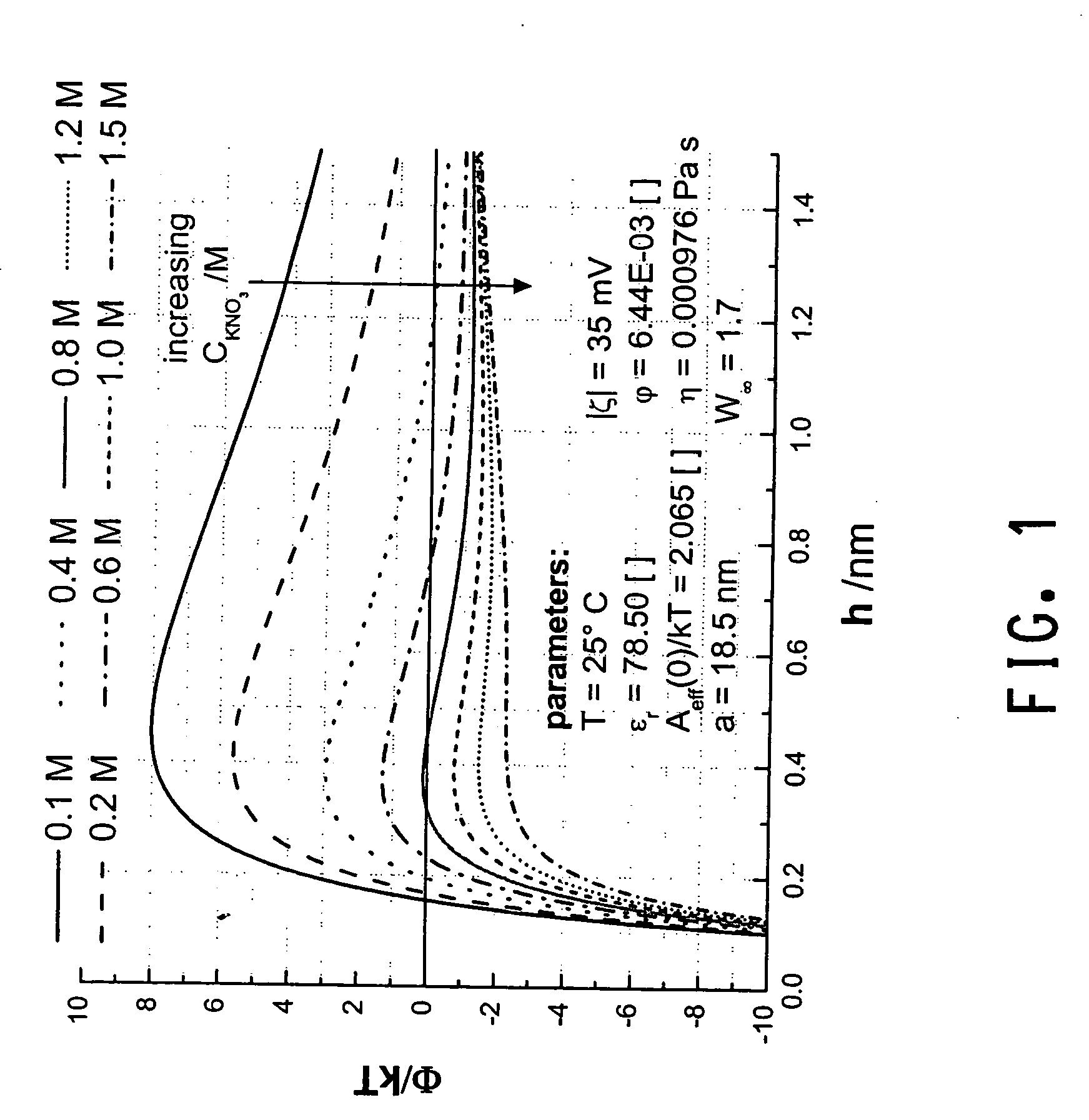
[0084] The particle agglomeration rate at different shear stresses was measured by dynamic light scattering (DLS). The colloidal silica (Ludox TM-50) was diluted to 5 wt.% in aqueous KOH to a pH of 8.84 and 0.2 M KNO3 and the suspension sheared in a high shear rheometer at 1000 s−1 for this purpose. A sample of the suspension was drawn at different times and the size of the agglomerates was measured with DLS. Perikinetic agglomeration was also measured for each sample. The sizes of the agglomerates were stable without applied shear stress.

example 2

[0085] Example 1 is repeated with a salt concentration of 0.4 M KNO3 instead of a 0.2 M KNO3. At 0.4 M KNO3 the energy barrier ΔEin is much lower than the energy barrier at 0.2 M KNO3. The agglomeration rate is measured in the same way and is much faster.


PUM

PropertyMeasurementUnit
sizeaaaaaaaaaa
flow rateaaaaaaaaaa
particle sizeaaaaaaaaaa

Abstract

This invention describes a process for agglomerating particles into fractal structures of designed size and distribution. The present invention relates generally to the production of particle agglomerates, tailored to a specific size and structure, from initially dispersed particles.

Description

FIELD OF THE INVENTION [0001] This invention describes a process for agglomerating particles into fractal structures of designed size and distribution in a dispersion. The present invention relates generally to the production of a slurry of particle agglomerates, tailored to a specific size and structure, and from dispersed particles. More particularly, it relates to the use of milling equipment such as media milling, rotor stator mixers, high-speed dispersers and fluid jet mills, to agglomerate an unstable or destabilized slurry to a specific structure. TECHNICAL BACKGROUND [0002] Dispersions of fine particles are often unstable, i.e. the particles tend to aggregate or agglomerate in a disorganized fashion. Often powders are comprised of assemblies of particles rather than single particles, and these particles are usually aggregated. Such assemblies are of limited commercial use and have to be processed further. Such processing is often difficult because, in aggregates, the particl...

Claims


Application Information

Patent Timeline
Patent Type & Authority Applications(United States)
IPC IPC(8): B01J2/10C08J3/16C09C1/44
CPCB01J2/10C08J3/16C08J3/12
Inventor GREEN, JOHN HENRYSOMMER, MARC MARTINSPAHR, DOUGLAS ERICWAGNER, NORMAN JOSEPH
Owner EI DU PONT DE NEMOURS & CO
Why Eureka
Try Eureka