

Method and network element for controlling power and/or load in a network
- Summary
- Abstract
- Description
- Claims
- Application Information
AI Technical Summary
Benefits of technology
Problems solved by technology
Method used
Image

Examples
Embodiment Construction
[0052] The preferred embodiments will now be described on the basis of an autotuning mechanism provided in a WCDMA radio connection of a radio access network.
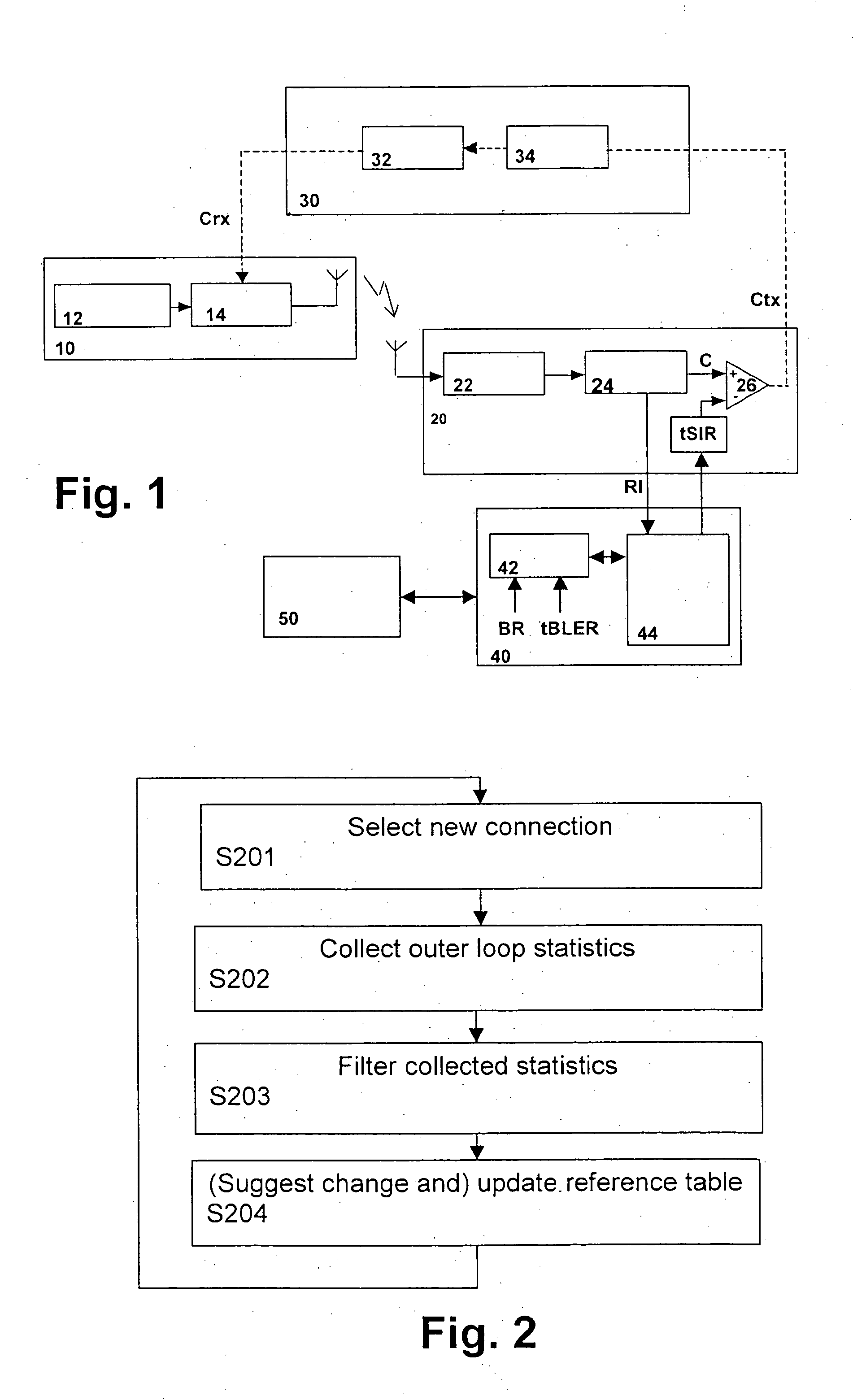
[0053]FIG. 1 shows a schematic block diagram of a transmission system according to the first preferred embodiment, wherein a terminal device 10, e.g. a mobile terminal or a user equipment, is connected by a radio transmission link to a node B or base station 20. In the mobile terminal 10, a WCDMA transmitter 12 is provided for generating a corresponding transmission signal to be supplied to a power amplifier 14 in which the transmission power is adjusted based on a received power command Crx, e.g. “up” or “down”, received via a return channel 30 from the base station 20. The return channel 30 comprises a radio network controller (RNC) channel 32 and a first-in-first-out (FIFO) register 34 in which subsequent power control commands for different slots are successively stored. The return channel 30 may be any feedback radio chan...
PUM
 Abstract
Description
Claims
Application Information