Robot operation program modification device

a technology of operation program and modification device, which is applied in the direction of programme control, total factory control, electric programme control, etc., can solve the problem of taking a long time for the work of modification, and achieve the effect of efficient and rational modification

Inactive Publication Date: 2005-05-19
FANUC LTD
View PDF0 Cites 11 Cited by
  • Summary
  • Abstract
  • Description
  • Claims
  • Application Information

AI Technical Summary

Benefits of technology

[0005] The present invention provides an operation program modification device capable of efficiently and rationally modifying a sequence of taught points which define an operation path at a corner, for instance, in the operation program. The present invention enables automatic modification of taught points other than one taught point which is modified by an operator in a sequence of taught points in the operation program.

Problems solved by technology

This arises a problem that it takes much time for the work of modification.

Method used


Image

  • Robot operation program modification device
  • Robot operation program modification device
  • Robot operation program modification device

Examples


first embodiment

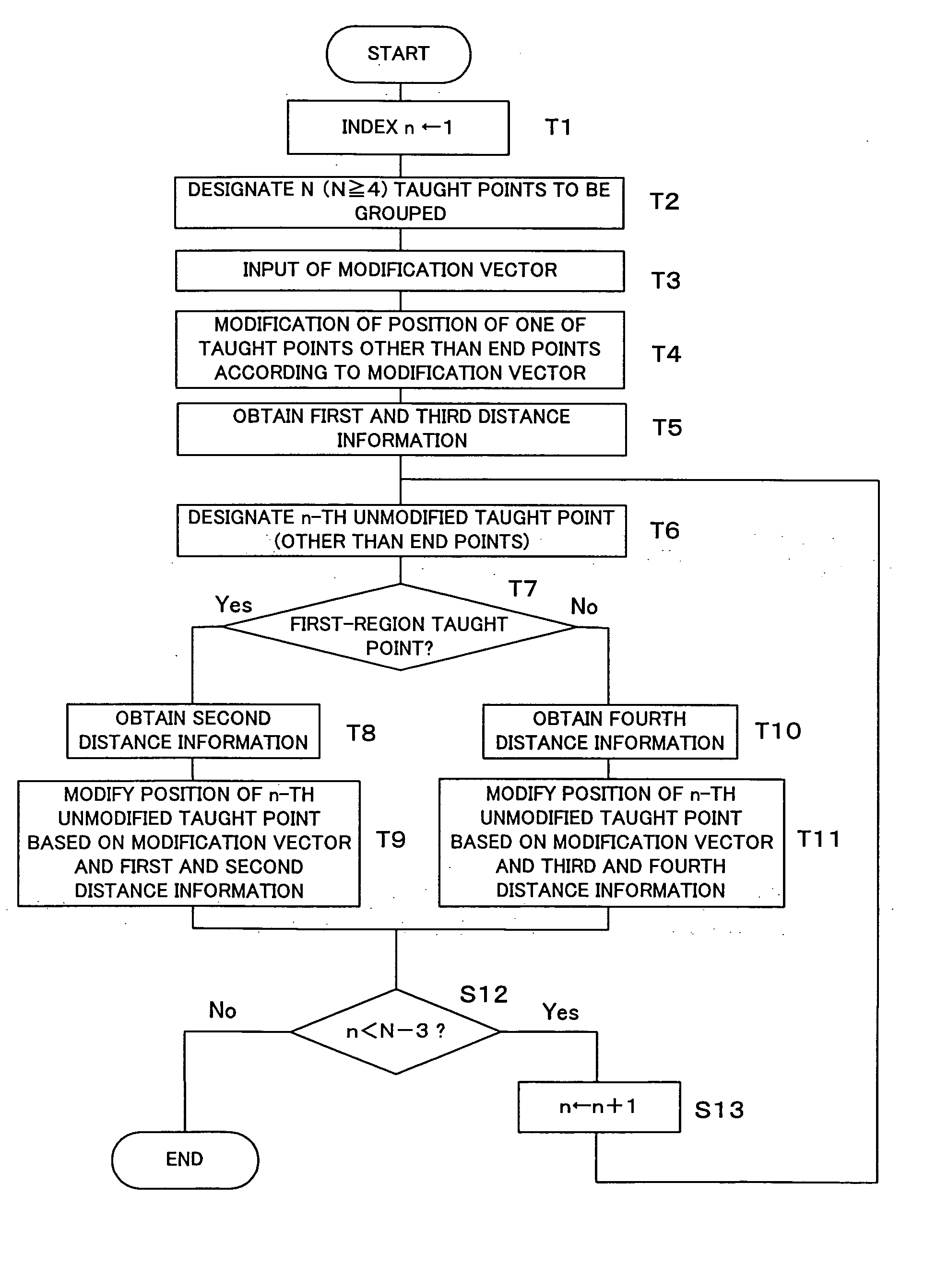
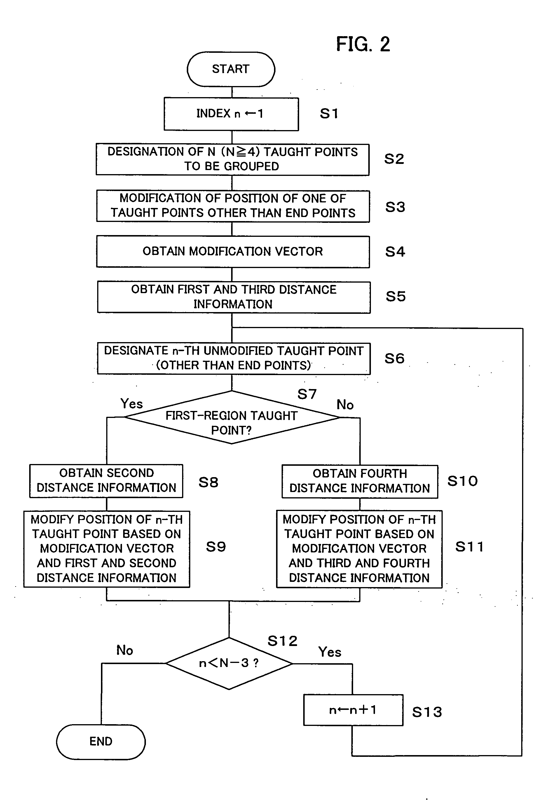
[0070] Step T4; an appropriate taught point is selected among N-2 taught points that remain after end points are excluded from N grouped taught points, to thereby make positional modification in accordance to the modification vector that is set in Step T2. According to the example mentioned in the first embodiment, the taught point A4 is selected from among the six taught points A1 through A6 shown in FIG. 3a, and the taught point that is modified by the modification vector becomes B4.

[0071] Step T5; first distance information D1 or D1′ is calculated. The calculation method is the same as the first embodiment.

[0072] Step T6; an n-th unmodified taught point is identified among taught points excluding both the end points (the first taught point and the final taught point) and the taught point selected in Step T4. The measurement method is the same as the first embodiment.

[0073] Step T7; it is judged in the system whether the taught point identified in Step T6 is a “first-region taug...

second embodiment

[0080] In the second embodiment, too, the taught points A2, A3 and A5 located in between the taught point A4 subjected to positional modification according to the modification vector that is set by the operator (user) and the end points A1 and A6 are grouped into the first-region taught points A2 and A3 and the second-region taught point A5. Moreover, required modification amounts of the taught points A2, A3 and A5 are calculated by prorating the modification vector according to distance (path distance or straight-line distance) from the end point A1 or A6.

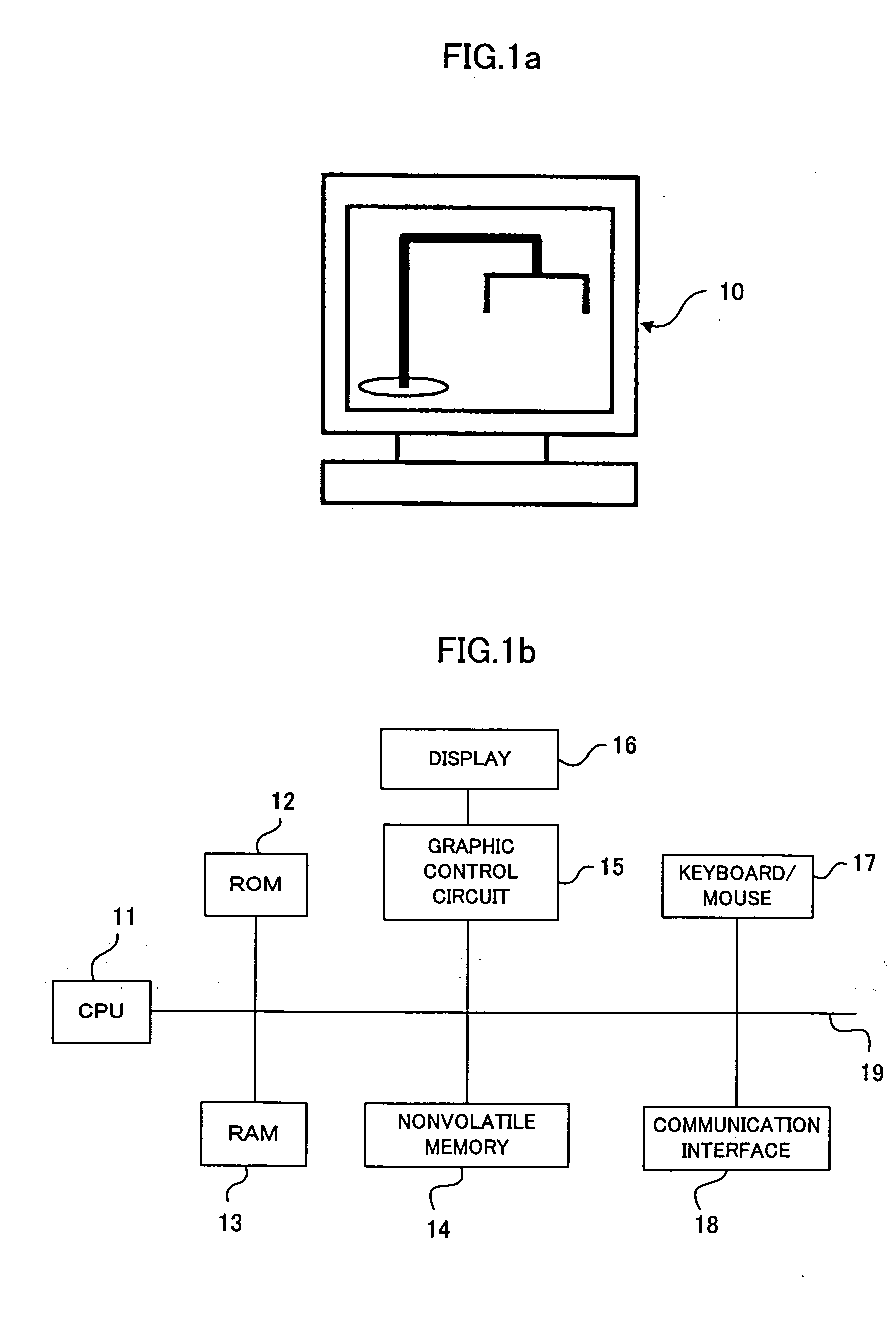
[0081] In the first and second embodiments, the offline programming system using the personal computer is utilized. In place thereof, however, a system including a teaching operation panel 20, a robot controller 30 connected to a peripheral device 40 and a robot mechanism 50, as illustrated in FIG. 5 may be utilized.

[0082] In that case, the unmodified program is prepared in the robot controller, and the modification on a set of t...


PUM


Abstract

An operation program modification device for a robot that is made efficient in positional modification of a cluster of taught points in a corner segment and the like. Sequential N taught points A1 through A6 to be grouped are designated, and the operator executes the operation of positional modification of an intermediate taught point A4. A modification vector for modifying A4 into B4 is calculated. Taught points A2, A3 and A5 located in between the taught point A4 and end points A1 and A6 are grouped into first-region taught points A2 and A3 and a second-region taught point A5. The required modification amounts of the taught points A2, A3 and A5 are calculated by prorating the modification vector according to distance (path distance or straight line distance) from the end-point A1 or A6 to be modified into taught points B2, B3 and B5, respectively. The modification vector may be set to correspond to a modified taught point of a user selection. It is possible to perform necessary input from a teaching operation panel instead of utilizing an offline programming system using a personal computer.

Description

BACKGROUND OF THE INVENTION [0001] 1. Field of the Invention [0002] The present invention relates to a technology for modifying an operation program for a robot, and more specifically to a technology for modifying taught point data in the operation program. [0003] 2. Description of Related Art [0004] As is well known, an operation program for a robot includes data of taught points, and an operation path defined by these taught points is called a taught path. When alternation of the taught path is required, the taught path is altered by modifying each position data of the taught points at a part of the taught path to be altered. In altering a corner part, for instance, of the taught path, it is often required to modify a plurality of taught points including those adjacent to the corner part. This arises a problem that it takes much time for the work of modification. Any specific effective proposal or suggestion to counter this problem is found in prior art documents. SUMMARY OF THE I...

Claims


Application Information

Patent Timeline
Patent Type & Authority Applications(United States)
IPC IPC(8): B25J9/22B25J9/16G05B19/42G05B19/425
CPCB25J9/1664G05B19/425G05B2219/40519G05B2219/36484G05B2219/36043Y02P90/02
Inventor WATANABE, ATSUSHIOUMI, TATSUYA
Owner FANUC LTD
Why Eureka
Try Eureka