Turbine tip clearance control system

a control system and turbine technology, applied in engine control, engine cooling apparatus, leakage prevention, etc., can solve the problems of nacelle loss, bleed air dumped, system limitation as to the minimum achievable tip clearance, etc., and achieve the effect of simple and cheap on-off valv

Inactive Publication Date: 2005-05-26
PRATT & WHITNEY CANADA CORP
View PDF22 Cites 64 Cited by
  • Summary
  • Abstract
  • Description
  • Claims
  • Application Information

AI Technical Summary

Benefits of technology

[0009] The valve may be a simple solenoid type “on-off” valve. In a preferred embodiment, the invention applies the concept of pulse width modulation (PWM) to this simple on-off valve. The method of the invention thereby achieves partial tip clearance control for certain mission conditions. Controlling blade tip clearance by selecting the air admission based on a duty cycle (PWM) has the advantage that a simple and cheap on-off valve may be used instead of a valve that is capable of various positions between fully open and fully closed.

Problems solved by technology

When operating the engine during a transitional period, the thermal response rates of the casing and the rotor blades are difficult to match, thereby resulting in a pinch-point.
This pinch-point causes a system limitation as to the minimum achievable tip clearance without rubbing.
Typically, this inter-stage compressor bleed air is dumped into the nacelle and lost to the cycle after having cooled the turbine casing.
The prior art offers complex solutions which do not maximize the efficiency of cooling air systems in the engine.

Method used


Image

  • Turbine tip clearance control system
  • Turbine tip clearance control system
  • Turbine tip clearance control system

Examples


Embodiment Construction

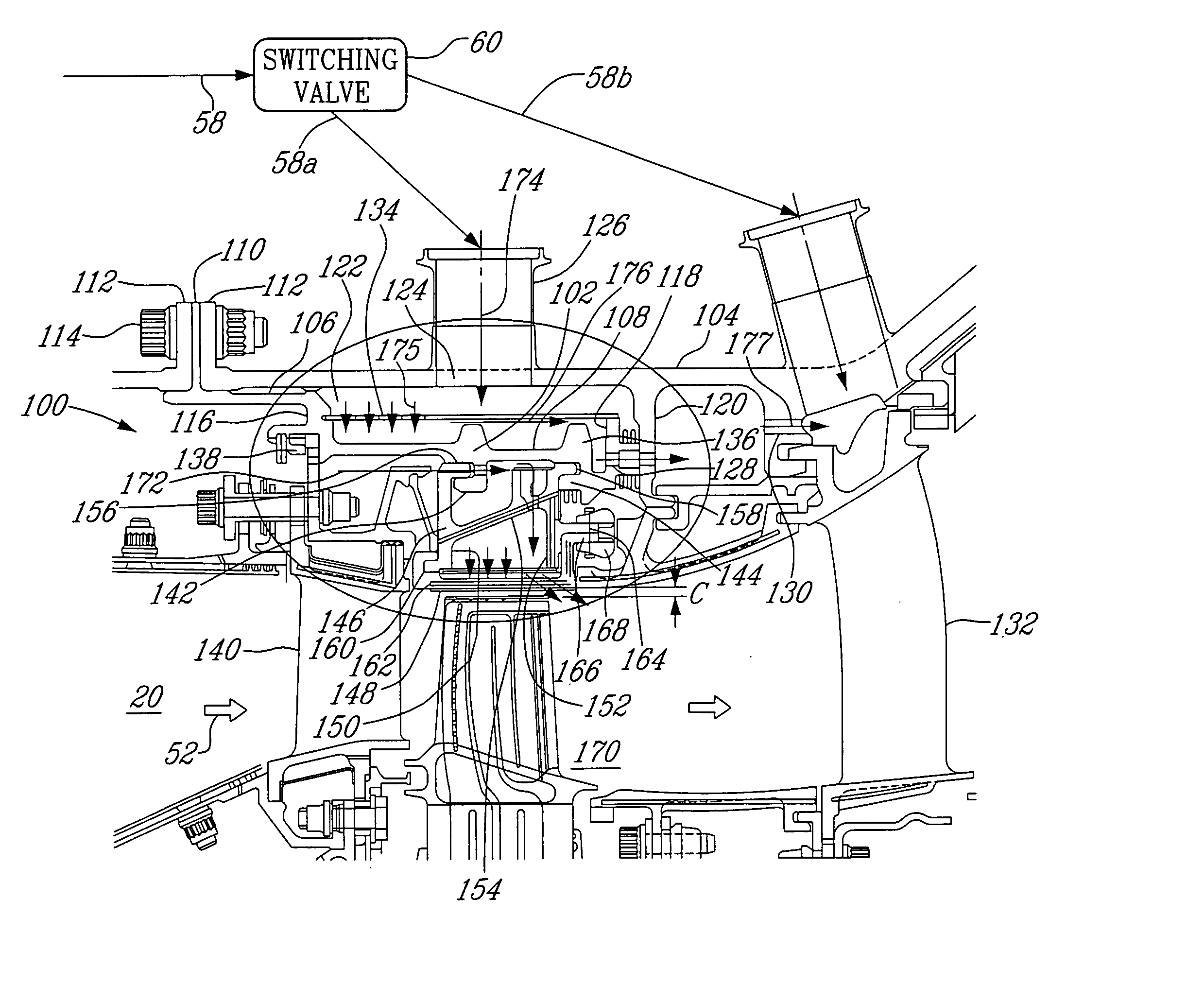
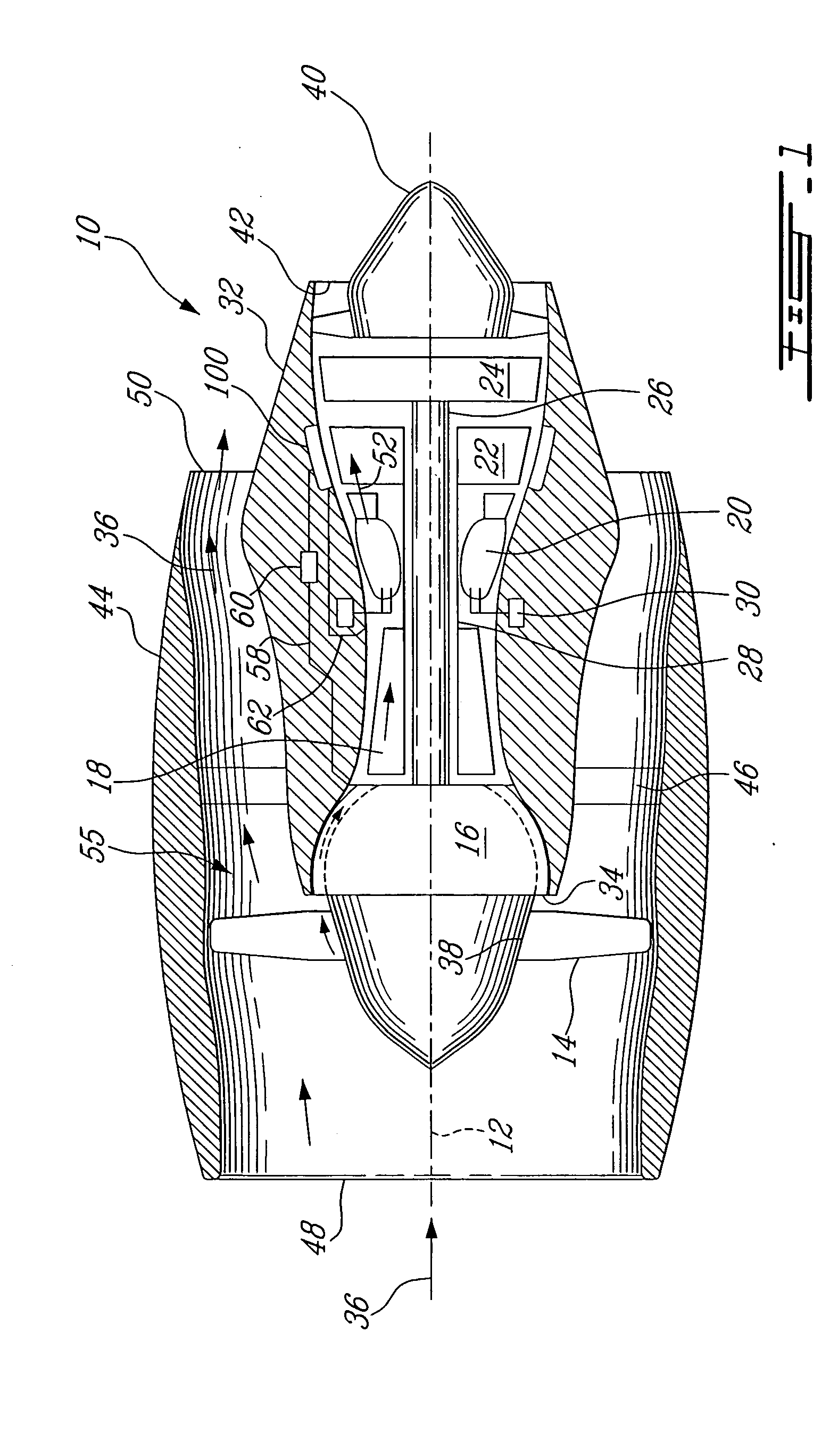
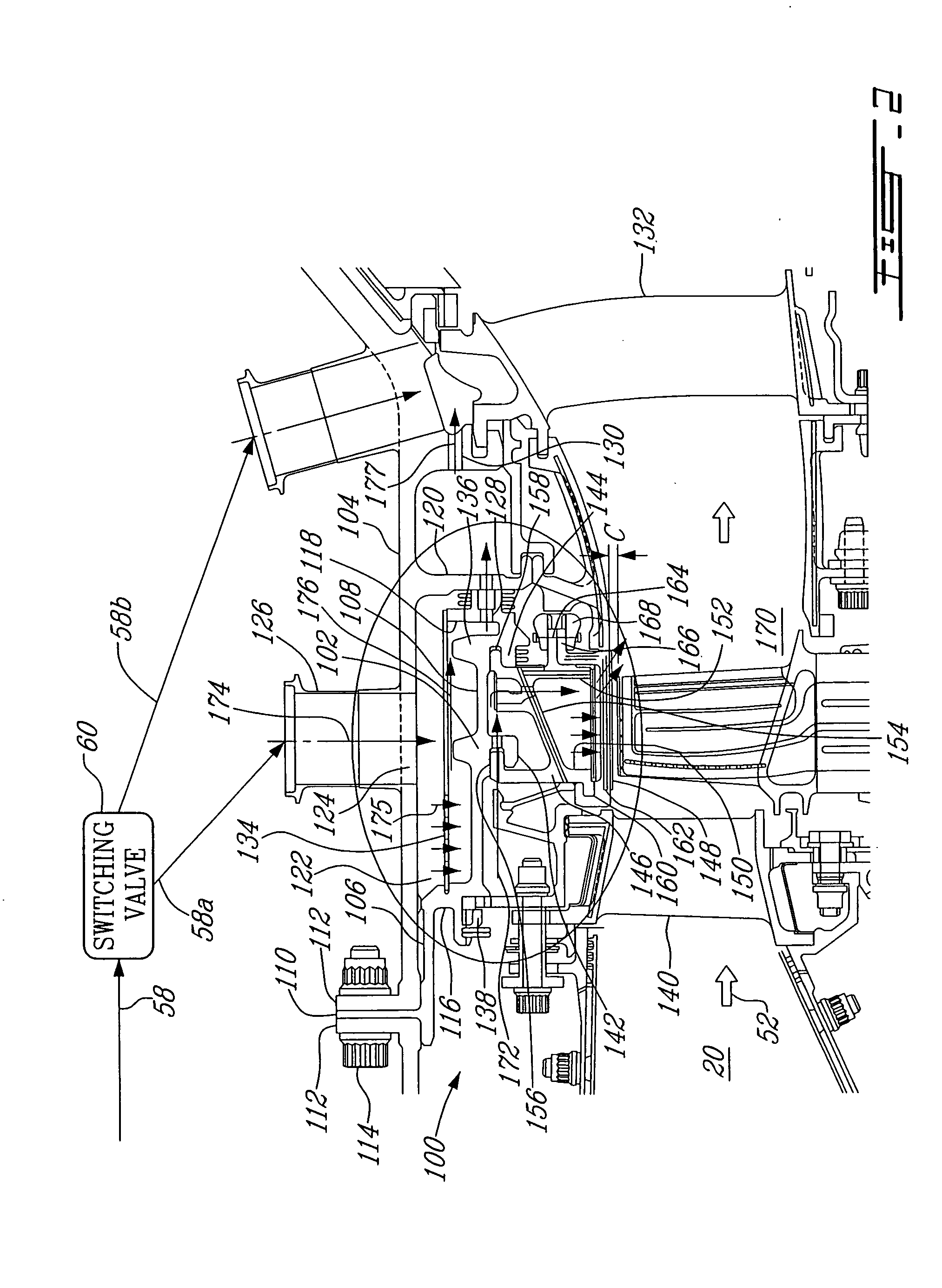
[0017] Referring to the drawings, particularly FIG. 1, an exemplary subsonic gas turbine engine 10 includes in serial flow communication a fan 14, a low pressure compressor 16, a high pressure compressor 18, a combustor 20, a high pressure turbine 22 which includes a turbine shroud support configuration 100 according to one embodiment of the present invention, and a low pressure turbine 24. The low pressure turbine 24 is operatively connected to the low pressure compressor 16 and the fan 14 by a first rotor shaft 26, and the high pressure turbine 22 is operatively connected to the high pressure compressor 18 by a second rotor shaft 28. Fuel injecting means 30 are provided for selectively injecting fuel into the combustor 20, for powering the engine 10.

[0018] An annular casing 32 surrounds the engine 10. Surrounding the casing 32 is a nacelle 44 which is spaced radially outwardly from the casing 32 to define an annular bypass duct 55. Inter-stage compressor bleed air is introduced b...


PUM


Abstract

An apparatus and method for selectively cooling a gas turbine engine component for the purpose of controlling blade tip clearance during transient conditions, wherein cooling air is admitted intermittently according to a desired a duty cycle based on a present or anticipated transient condition.

Description

FIELD OF THE INVENTION [0001] The present invention generally relates to gas turbine engines, and more particularly to clearance control between turbine rotor blade tips and a stator shroud assembly radially spaced apart therefrom. BACKGROUND OF THE INVENTION [0002] It is desirable to maintain the clearance gap between turbine blade tips and the static shroud assembly as small as possible throughout the engine operation range because the gap is essentially inversely proportioned to efficiency. However, because the material of the stator components and the turbine rotor are different, and because thermal inertia has an influence on the expansion of the rotor, the stator components, the engine case, outer air seal, and support mechanism all expand at different rates. Therefore, the gap must be sized larger than would otherwise be desirable to avoid the possibility of contact at certain transient conditions. When operating the engine during a transitional period, the thermal response r...

Claims


Application Information

Patent Timeline
Patent Type & Authority Applications(United States)
IPC IPC(8): F01D11/24F02C9/18
CPCF01D11/24F05D2270/303F05D2270/44F02C9/18
Inventor ULLYOTT, RICHARD
Owner PRATT & WHITNEY CANADA CORP
Why Eureka
Try Eureka