

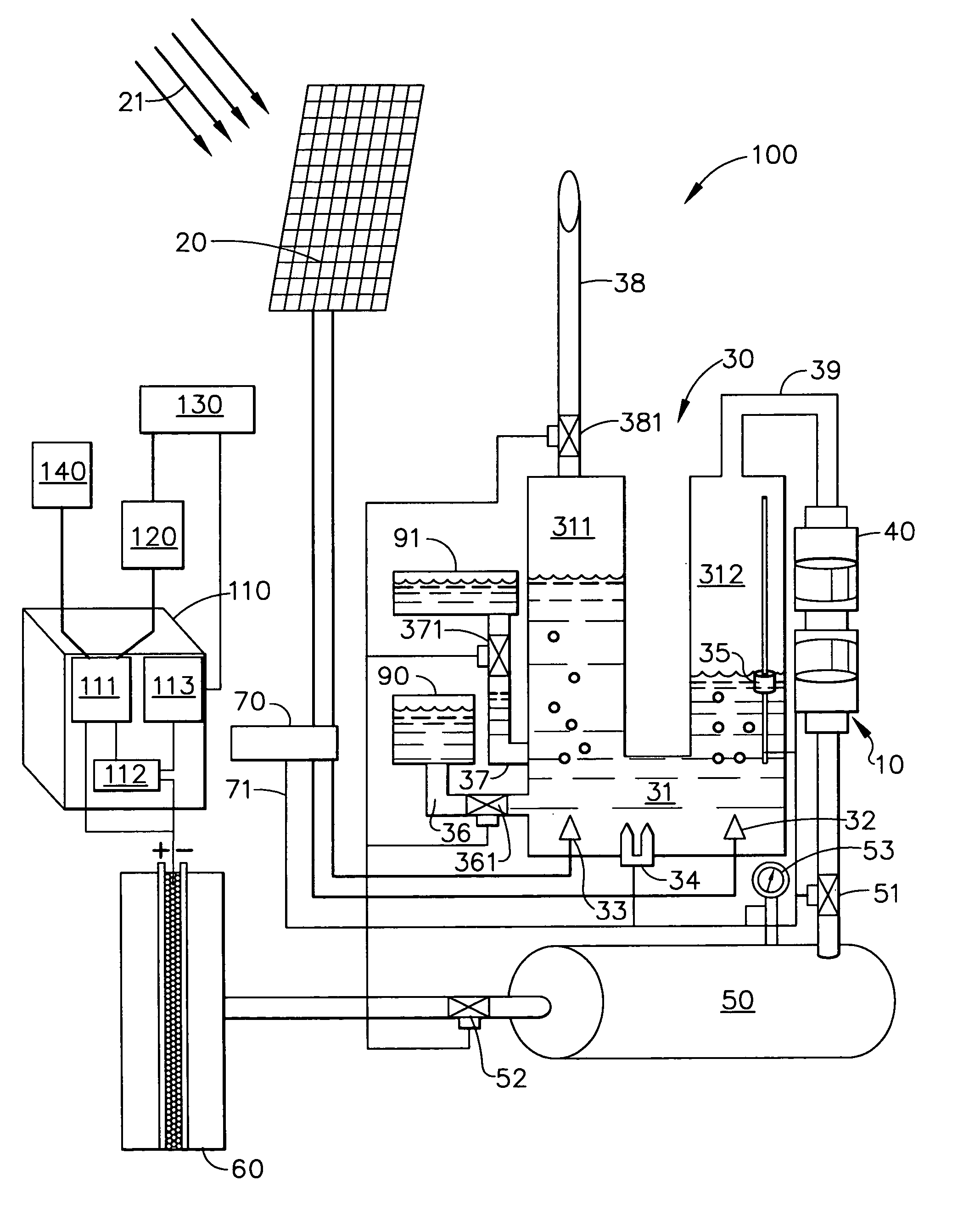
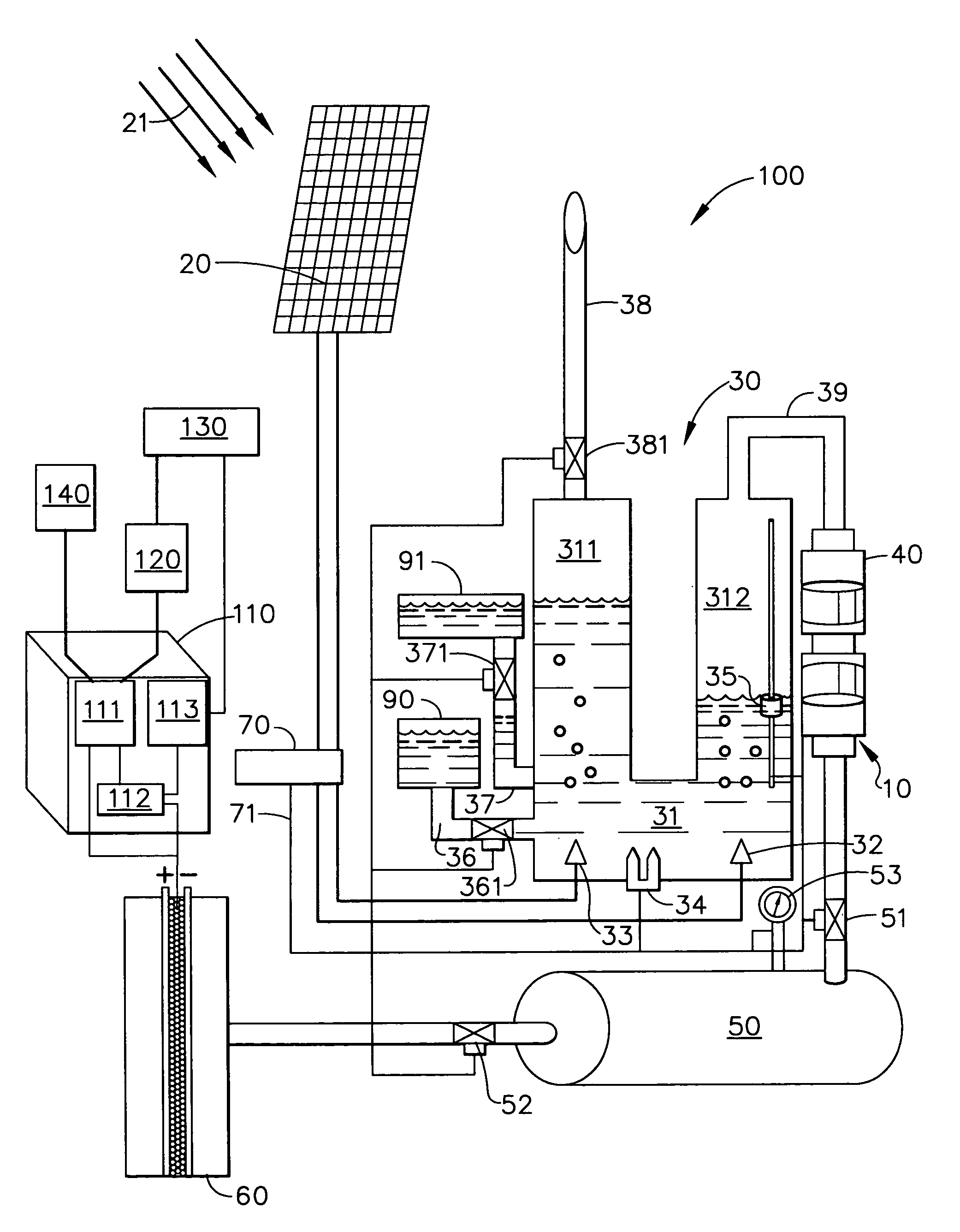
Solar electrolysis power co-generation system
a co-generation system and solar energy technology, applied in the direction of energy input, greenhouse gas reduction, electric circuit machining, etc., can solve the problems of long lead time and high cost of new power plants and power transmission systems, and many existing state and municipal power grids are incapable of handling peak loads
- Summary
- Abstract
- Description
- Claims
- Application Information
AI Technical Summary
Benefits of technology
Problems solved by technology
Method used
Image

Examples
Embodiment Construction
[0018] The following detailed description is of the best currently contemplated modes of carrying out the invention. The description is not to be taken in a limiting sense, but is made merely for the purpose of illustrating the general principles of the invention, since the scope of the invention is best defined by the appended claims.
[0019] Broadly, an embodiment of the present invention provides a solar electrolysis power co-generation system that utilizes the electrolysis of water and solar energy to power a fuel cell and to produce electrical power. The produced electrical power may be used to provide power to an individual consumer, such as houses, municipal buildings, hospitals, and manufacturing plants, as well as to an existing power grid as needed. Other uses of the solar electrolysis power co-generation such as supplying power to individual consumers in remote geographic areas as a stand-alone solution or in addition to existing power supplies are possible. Contrary to kn...
PUM
| Property | Measurement | Unit |
|---|---|---|
| Electric potential / voltage | aaaaa | aaaaa |
| Frequency | aaaaa | aaaaa |
| Pressure | aaaaa | aaaaa |
Abstract
Description
Claims
Application Information