Level measurement for grease separators

a technology for level measurement and grease separators, which is applied in the direction of liquid displacement, separation process, instruments, etc., can solve the problems of not all manual interceptors are constructed of metal, not all are compatible with level measurement systems, and it is not practicable to design a custom level measurement system for each tank

Inactive Publication Date: 2005-05-26
MAZUREK NIEL +2
View PDF11 Cites 21 Cited by
  • Summary
  • Abstract
  • Description
  • Claims
  • Application Information

AI Technical Summary

Problems solved by technology

Scheduled inspections may occur after the tank has already filled and grease has begun to flow into the sewer system, creating a significant problem.
Another unmet need in the market arises from the fact that there is large variety of existing manual interceptor tank sizes and sh

Method used


Image

  • Level measurement for grease separators
  • Level measurement for grease separators
  • Level measurement for grease separators

Examples


Embodiment Construction

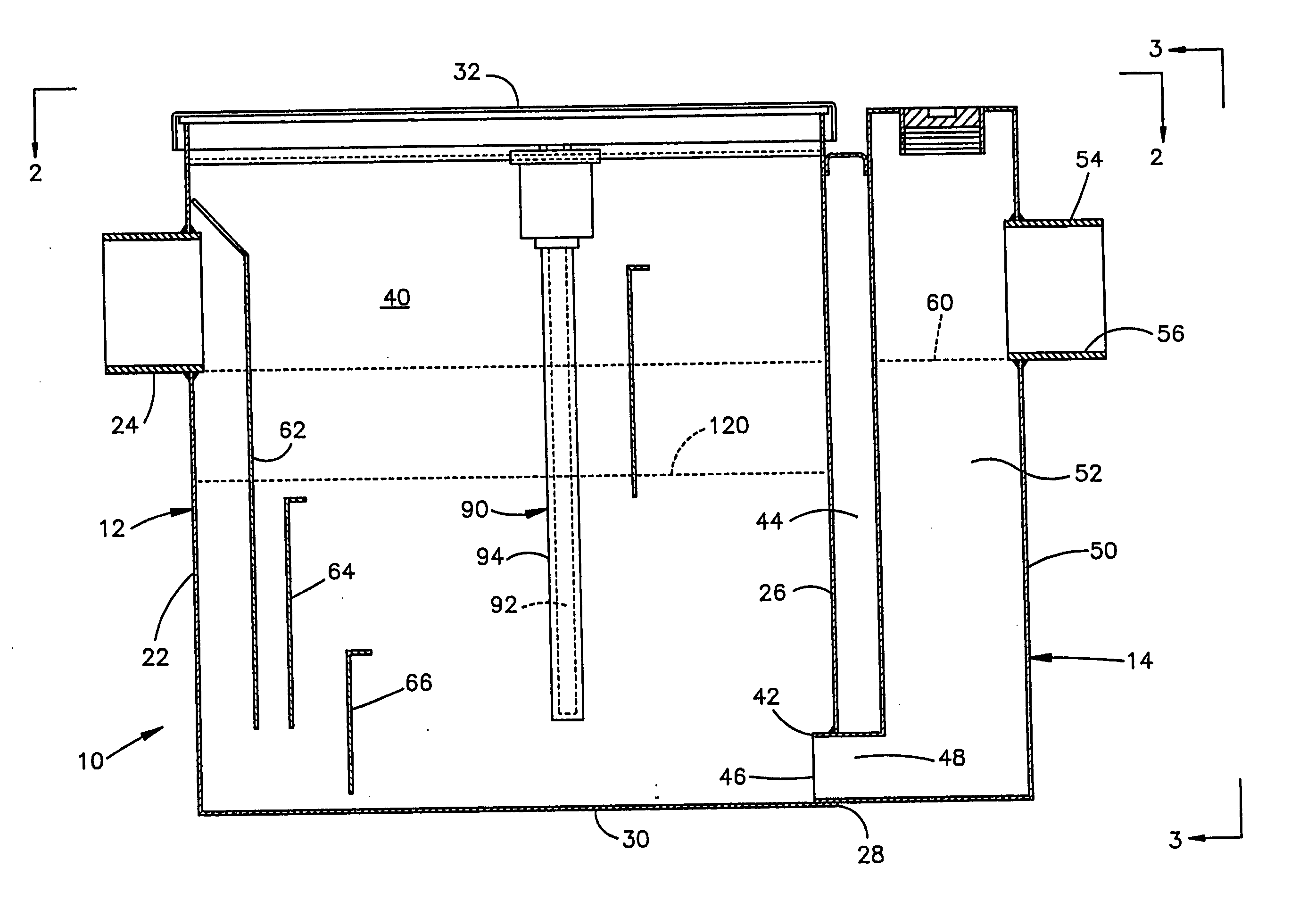
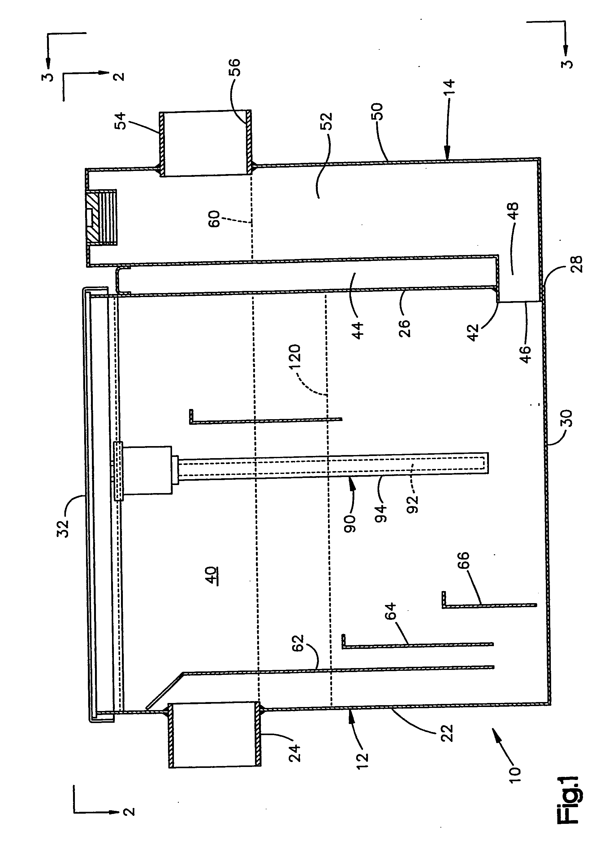
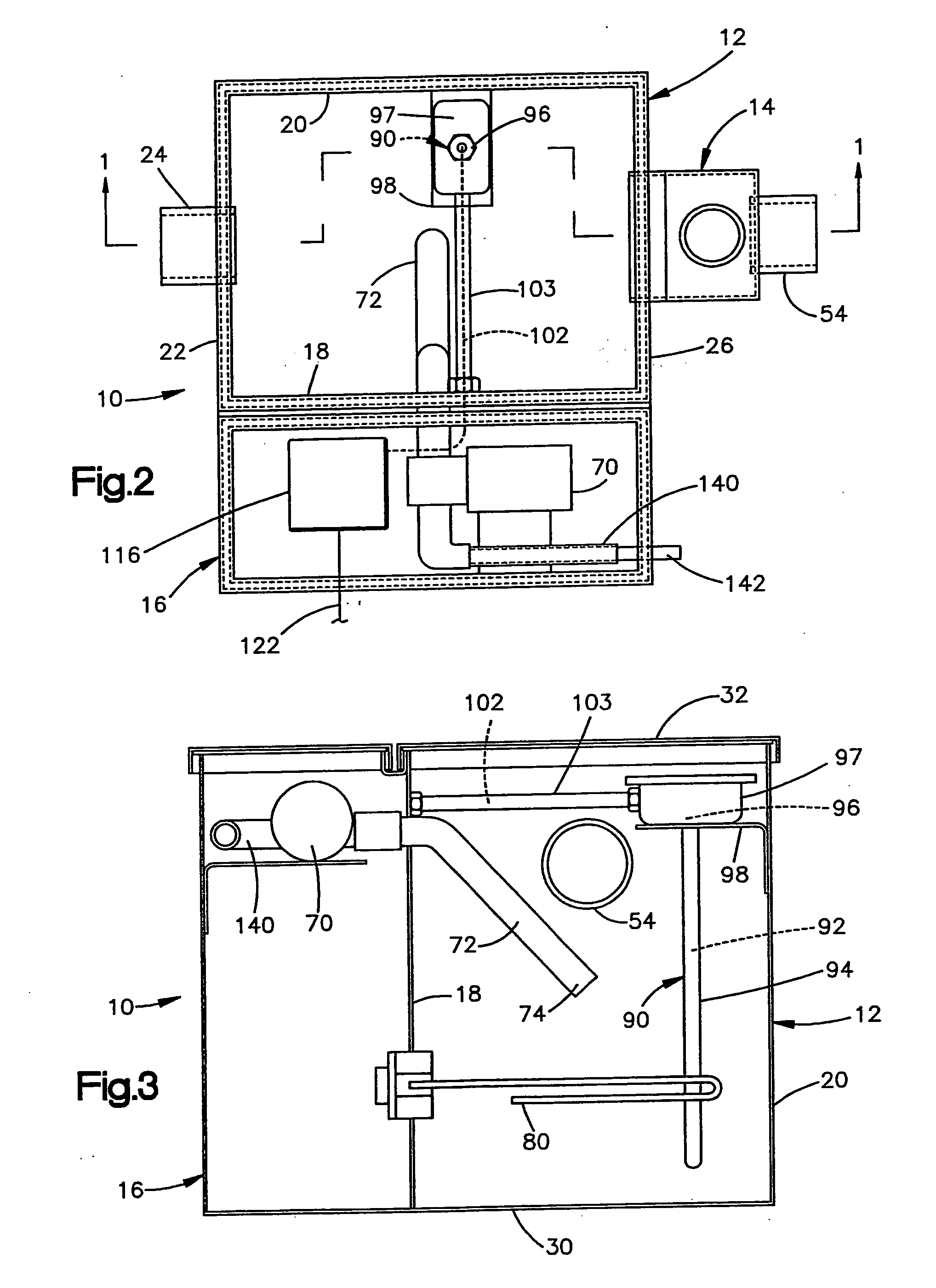
[0022] The present invention relates to apparatus for separating grease from effluent containing grease and water. The present invention is applicable to grease separators (interceptors) of various constructions, as shown and otherwise. As representative of the present invention, FIGS. 1-4 illustrate an interceptor 10 in accordance with a first embodiment of the invention. The interceptor 10 includes a separation tank 12 and a trap leg 14. An equipment cabinet 16 is connected to the separation tank 12.

[0023] The separation tank 12 is made from an electrically conductive material, such as metal, and includes a front wall 18 (FIG. 2) and an opposite back wall 20. An inlet wall 22 interconnects the front and back walls 18 and 20. An inlet 24 extends through the inlet wall 22. At its opposite end the separation tank 12 includes an end wall 26 (FIG. 2). The end wall 26 has a rectangular opening 28 into the trap leg 14.

[0024] The separation tank 12 also has a bottom wall 30 and a remova...


PUM

PropertyMeasurementUnit
Lengthaaaaaaaaaa
Thicknessaaaaaaaaaa
Lifetime stabilityaaaaaaaaaa

Abstract

The present invention relates to apparatus for removing grease from an effluent stream containing grease and water. A separation tank defines a separation chamber. An effluent inlet connected with the separation tank permits flow of the effluent stream into the chamber to form a body of effluent in the separation chamber. A grease depth level sensor is used in determining the amount of grease in the body of effluent. The interceptor may be queried remotely to check its status. In one embodiment, an output signal indicative of the amount of grease is transmitted over a telephone line to a telephone or computer or other remote station. Alternatively, the output signal is transmitted wirelessly to a remote receiver. The status is preferably also indicated locally with visual and/or audible signals. The sensor is preferably a capacitive level sensor operative to sense the amount of water in the body of effluent thereby to determine the amount of grease in the body of effluent. The interceptor may include electric circuitry for effecting manual or automatic calibration of the grease depth level sensor. The sensor may be adapted to be retrofitted to an existing tank made from either metal or plastic.

Description

RELATED APPLICATION [0001] This application is a continuation in part of U.S. patent application Ser. No. 09 / 627,389, filed Jul. 28, 2000, entitled Continuous Level Measurement For Grease Separator, and this application claims the benefit of the filing date of all common subject matter.BACKGROUND OF THE INVENTION [0002] The present invention relates to an apparatus for recovering grease from a grease separator. In particular, the present invention relates to a sensor operative for sensing the presence of a thickened layer of grease in a body of effluent. [0003] It is known to pass the effluent from food processing facilities or other operations through devices for removing grease, to enable the grease to be kept out of a sewage system. Some such devices use a sensor for sensing the presence of a thickened layer of grease in the body of effluent in the device. The output of the sensor is then used to control pumping of grease from the device. An example of such a device is the automa...

Claims


Application Information

Patent Timeline
IPC IPC(8): B01D17/00B01D17/12C02F1/00C02F1/02C02F1/40G01F23/26G05D9/12
CPCB01D17/005C02F1/008C02F1/02C02F1/40C02F2103/32C02F2209/02C02F2209/40G05D9/12G01F23/268G01F23/266B01D17/0208B01D17/0211B01D17/0214
Inventor MAZUREK, NIELHOLLOWAY, B. SCOTTTESVIS, CHARLES
Owner MAZUREK NIEL
Why Eureka
Try Eureka