Apparatus for treating storm water

a technology for storm water and apparatus, applied in water/sewage multi-stage treatment, liquid displacement, separation process, etc., can solve the problems of not being able to remove both floating and high flow that bypasses the low flow treatment chamber, and achieve the effect of reducing the volume of storm water runo

Active Publication Date: 2005-05-26
BRYANT GRAHAM
View PDF18 Cites 25 Cited by
  • Summary
  • Abstract
  • Description
  • Claims
  • Application Information

AI Technical Summary

Benefits of technology

[0019] In an alternative embodiment, and which is optional, there can also be a filter/recharge chamber provided that receives the water from the second treatment chamber and which has, therefore, been treated by both the first and second treatment chambers. In the filter/recharge chamber, th...

Problems solved by technology

One of the difficulties in the removal of such materials from stormwater is the need to take into account different flows of that water.
In such treatment facilities, however, the high flow that bypasses the low flow treatment chambers is not normally treated to remove both floating and non-floating materials.
Accor...

Method used


Image

  • Apparatus for treating storm water
  • Apparatus for treating storm water
  • Apparatus for treating storm water

Examples


Embodiment Construction

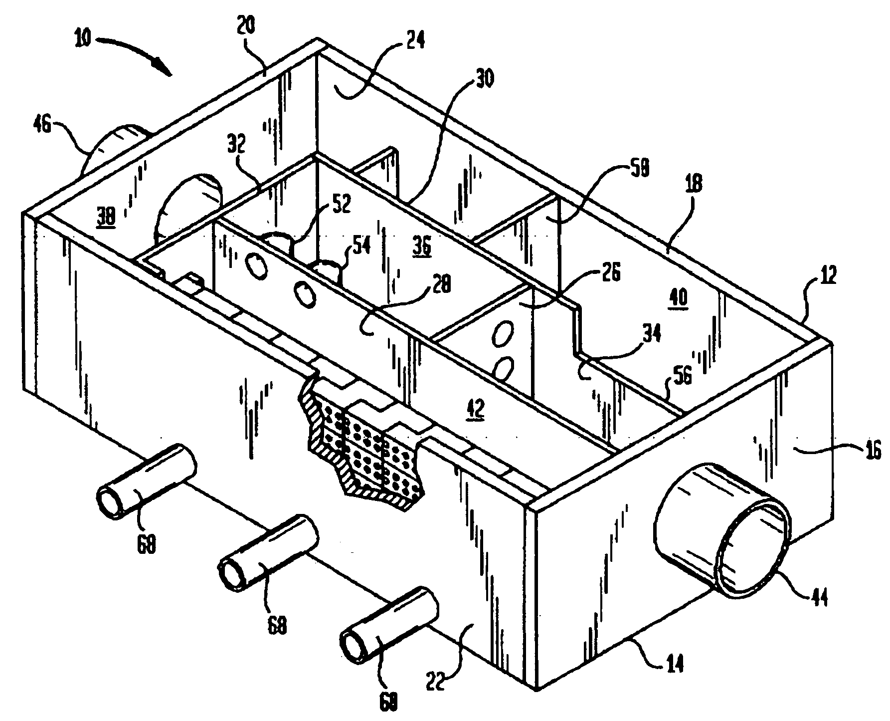
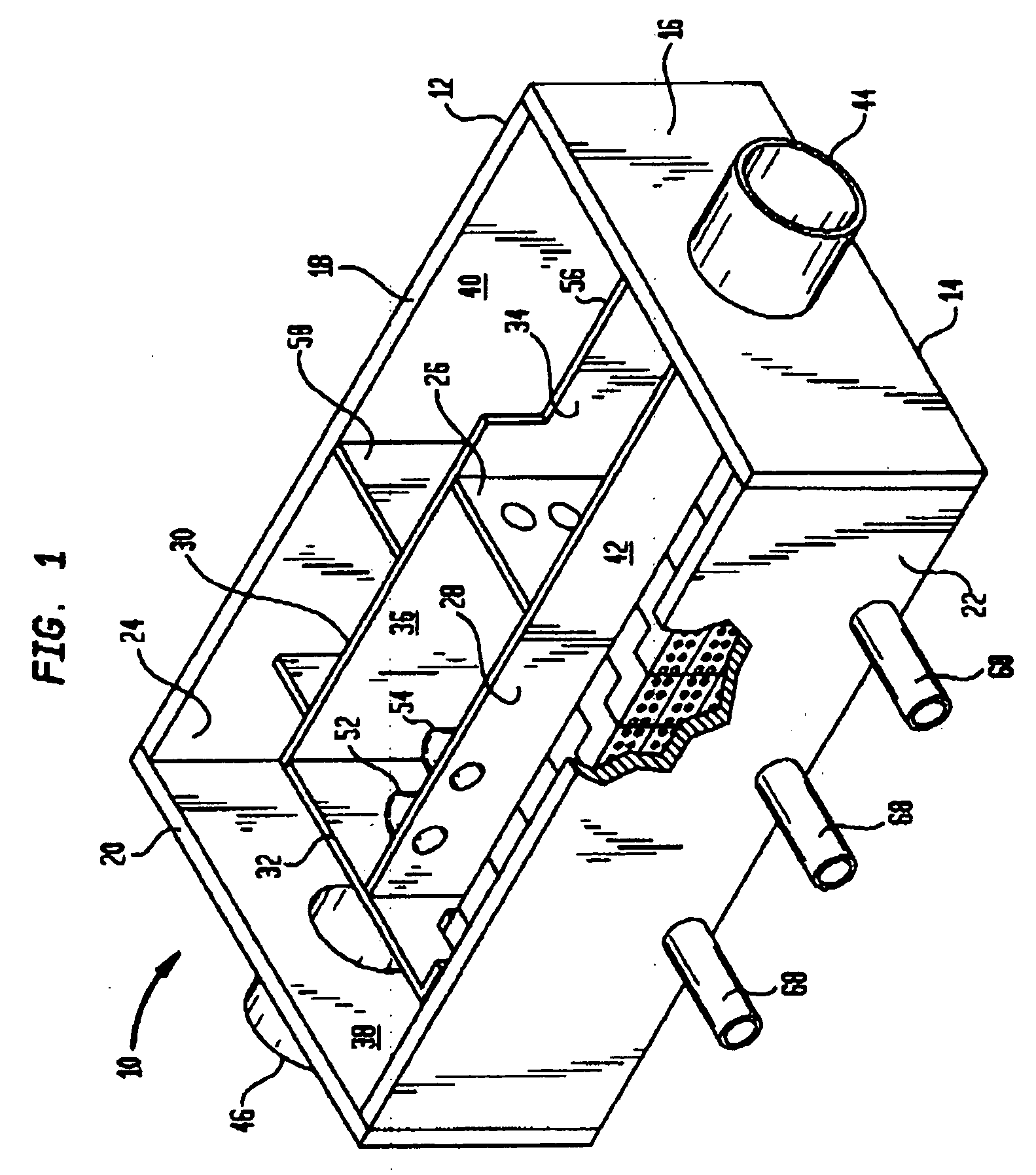
[0027] Referring now to FIG. 1, there is shown a separation tank 10 that comprises a container 12 having a bottom 14 and four side walls 16, 18, 20 and 22 that form a generally rectangular enclosure that also includes a cover 24 that is basically designed to cover that enclosure and is normally affixed to the upper ends of each of the side walls 16, 18, 20 and 22. The side walls 16, 18, 20, 22 bottom 14 and cover 24 can be constructed of a solid building material such as, but not limited to, concrete or metal.

[0028] Within that enclosure, there are located a plurality of partitions that divide the interior of the container 12 into a plurality of chambers and, as can be seen, those partitions are identified as a first partition 26, a second partition 28, a third partition 30 and a fourth partition 32.

[0029] Thus, the plurality of chambers that are formed by the partitions 26, 28, 30 and 32 are a first treatment chamber 34, a second treatment chamber 36, an outlet chamber 38, a high...


PUM

PropertyMeasurementUnit
Flow rateaaaaaaaaaa
Heightaaaaaaaaaa

Abstract

A separation tank having an inlet and an outlet and forming a low flow path and a high flow path, both conveying water from the inlet to the outlet. At normal, low flows, the water enters the inlet and passes through the low flow path having treatment chambers to remove, respectively, heavy materials and floatable materials. At high flows such as with heavy storm runoff, water exceeding a predetermined flow rate is conveyed from the low flow path into the high flow path where there are baffles to treat the water to remove both heavy materials and floatable materials. In optional embodiments, there is a filter/recharge chamber that may contain a filter and/or a groundwater conveyance system such that filtered or unfiltered water can be discharged from the low flow path through a groundwater conveyance system to groundwater, to the normal outlet, or both.

Description

TECHNICAL FIELD [0001] The present invention relates generally to a device for treatment of storm water, and, more particularly, to an apparatus that provides treatment to the water both during normal flows and also during the high flows occasioned by a heavy downpour. BACKGROUND OF THE INVENTION [0002] In the treatment of storm water, it is necessary to remove various undesirable elements and components, such as bacteria, oil, metals, nutrients, trash and a number of other solids. Many of the pollutants bond to the finer sediment and which is the reason many regulatory agencies now focus on total suspended solids (TSS) as a criteria for design / approval of stormwater quality measures. [0003] To that end, the Clean Water Act requires some stormwater quality treatment for all new developments over 0.5 acres in size. Many types of equipment and processes have been suggested for dealing with this problem. [0004] One of the difficulties in the removal of such materials from stormwater is...

Claims


Application Information

Patent Timeline
IPC IPC(8): B01D21/00C02FC02F7/00E03F5/12
CPCB01D21/0012B01D21/003B01D21/0042B01D21/0051B01D21/0069E03F5/125B01D21/30B01D2221/12C02F2103/001E03F5/12B01D21/10
Inventor BRYANT, GRAHAM
Owner BRYANT GRAHAM
Why Eureka
Try Eureka