System and method for inputting contours of a three-dimensional subject to a computer

a three-dimensional subject and computer technology, applied in the field of system and method for inputting contours of three-dimensional subjects to computers, can solve the problems of limited commercialization of technology, large amount of processor resources, and stretch the limits of currently available computer systems, so as to simplify electronic processing, easy to distinguish, and easy to distinguish

Inactive Publication Date: 2005-05-26
PERRY MICHAEL +1
View PDF3 Cites 16 Cited by
  • Summary
  • Abstract
  • Description
  • Claims
  • Application Information

AI Technical Summary

Benefits of technology

[0036] It is according a first objective of the invention to provide a simple and inexpensive system and method for inputting contours of a subject to a computer or other electronic processing device.
[0037] It is a second objective of the invention to provide a system and method for establishing contours of the subject in a way that eliminates the need for feature extraction, interpolation, and other complex image processing software or algorithms.
[0040] It is a fifth objective of the invention to provide a system and method for capturing contours of a three-dimensional subject that enables correlation of superposed grid lines and a visible light image of the subject, while permitting direct analysis of the grid lines without the need for electronically separating the grid lines from the visible light image of the subject.
[0043] The objectives of the invention are still further accomplished by providing a system and method for capturing contours of a three-dimensional subject which uses infrared light to form at least one grid so as to easily distinguish the at least one grid from a composite image of the subject and grid, and which in the case where multiple grids are used to achieve a stereoscopic effect without the need for multiple cameras, uses different infrared frequencies so that the multiple grids may more easily be distinguished from each other.
[0044] The objectives of the invention are also accomplished by providing a system and method for capturing contours of a three-dimensional subject which uses optical separation of a grid from the composite image so as to simplify electronic processing, and which in the case where multiple grids are used to achieve a stereoscopic effect without the need for multiple cameras situated at different angles, uses optical separation of the multiple grids from each other so as to further simplify subsequent electronic processing.

Problems solved by technology

All of these applications require substantial processor resources, and even the simplest such systems tend to stretch the limits of currently available computer systems.
The technology for utilizing three-dimensional data input is developing rapidly, but commercialization of the technology has been limited by either (i) the cost and complexity of current data input hardware and control software, or (ii) if simpler input means are used, the cost and complexity of image processing software necessary to make sense of the data.
As a result, this system shares with other prior systems Because the grid is formed by visible light, this system shares with other prior systems the problem of separating the grid from background.
However, the use of laser scanning in the system of this patent makes the system much more complicated than is the case with a system that uses multiple light frequencies.
U.S. Pat. No. 5,235,416 discloses use of two cameras sensitive to different wavelengths, and two corresponding illumination sources to simultaneously image two sides of an object without interference, but does not disclose any sort of grid.

Method used


Image

  • System and method for inputting contours of a three-dimensional subject to a computer
  • System and method for inputting contours of a three-dimensional subject to a computer
  • System and method for inputting contours of a three-dimensional subject to a computer

Examples


Embodiment Construction

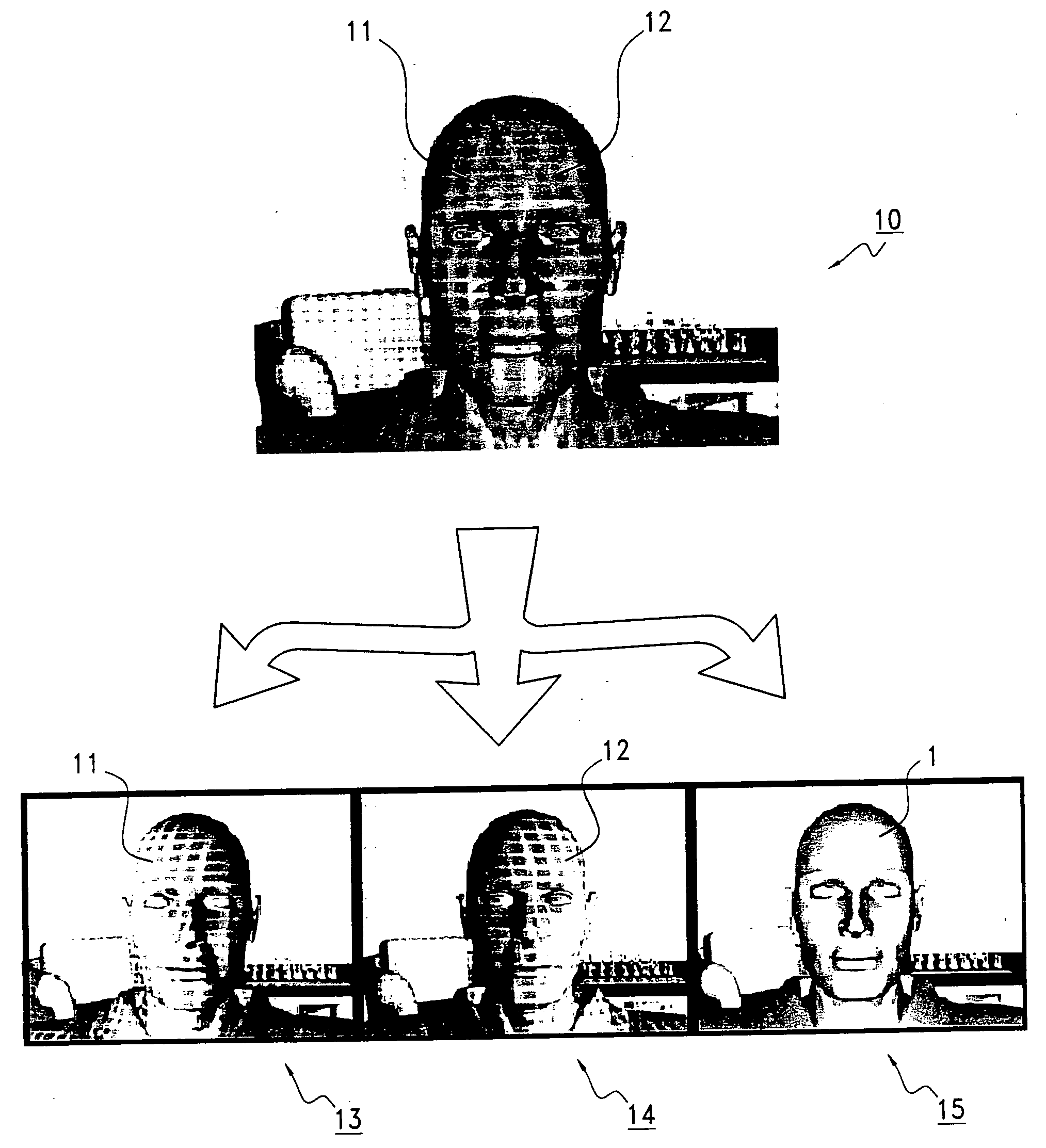
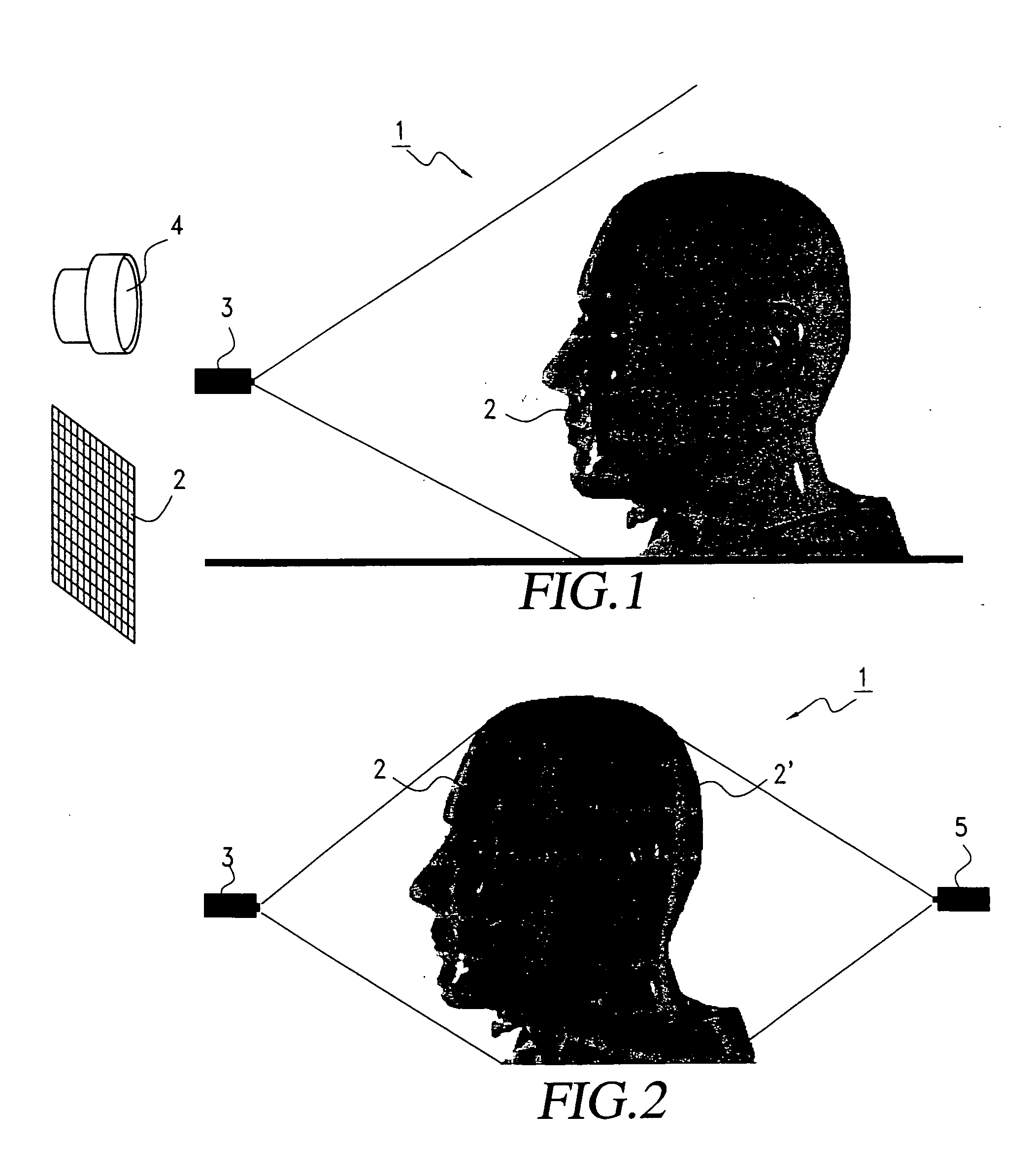
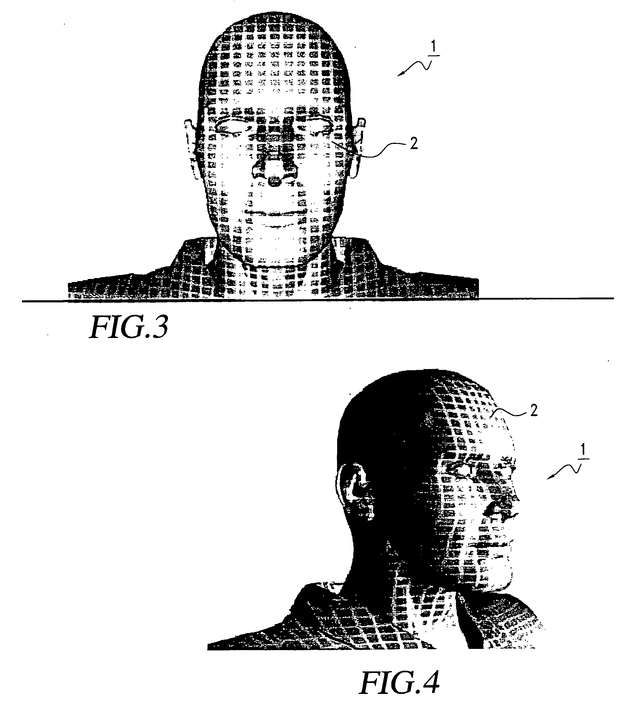
[0055]FIG. 1 illustrates an embodiment of the invention in which the subject 1 is illuminated by a single infrared grid 2 projected from the front of the subject by a projector 3. The subject 1 may also be illuminated by a substantially uniform light source 4, by multiple light sources, or by ambient light.

[0056] In a variation of the embodiment of FIG. 1, multiple grids 2 and 2′ may be projected onto the subject in order to enable capture of contours for the entire 360° of the subject by using an additional camera 5 (or, equivalently, by moving projector 3 around the subject), as illustrated in FIG. 2.

[0057] Each grid shown in FIGS. 1 and 2 is preferably an infrared grid having a wavelength of sufficient intensity to enable an image of the grid to be captured despite background infrared radiation that might be emitted by the subject, and is made up of mutually perpendicular horizontal and vertical lines. Suitable infrared light sources are well-known, as are cameras and film capa...


PUM


Abstract

At least one two-dimensional infrared grid is projected onto a three-dimensional subject in order to determine or represent contours of the subject based on distortion of the grid. The grid is separated from a composite visible-infrared image by a beam splitter. If two grids are superposed for a stereoscopic effect, the two grids preferably have different infrared wavelengths and are separable by a second beam splitter.

Description

BACKGROUND OF THE INVENTION [0001] 1. Field of the Invention [0002] This invention relates to a system and method for enabling input, to a computer or other electronic processing device, of data concerning the three-dimensional contours or profiles of an inanimate or animate subject. [0003] The invention involves projecting one or more infrared grids or similar patterns onto the subject, the projected infrared grid(s) or pattern(s) reflecting contours of the subject. The subject may be illuminated by any type of illumination, including visible light, so long as the resulting image of the subject can be distinguished from the image or images of the infrared grid or grids (or other patterns, hereinafter referred-to simply as “grids”). [0004] Preferably, the image or images of the infrared grid or grids are optically separated from the image of the subject by using a beam splitter that transmits or reflects the respective images of the grid or grids and subject to different detectors t...

Claims


Application Information

Patent Timeline
Patent Type & Authority Applications(United States)
IPC IPC(8): G01B11/25H04N13/00H04N13/02
CPCG01B11/2509G01B11/2513G01B11/2531H04N13/0253H04N13/021H04N13/0246H04N13/0207H04N13/211H04N13/254H04N13/246H04N13/207
Inventor MYERS, KENNETH J.
Owner PERRY MICHAEL
Why Eureka
Try Eureka