Edge-holding aligner

a technology of a clamping and a clamping plate, which is applied in the direction of printing machines, instruments, electrical equipment, etc., can solve the problems of incorrect positioning of the substrate, inability to properly detect the notch, and long position adjustment procedure using the prior aligner, so as to reduce the possibility of the thus correctly placed substrate being dislocated during the transfer operation, reduce the teaching time, and secure the effect of holding

Active Publication Date: 2005-05-26
KAWASAKI HEAVY IND LTD
View PDF3 Cites 20 Cited by
  • Summary
  • Abstract
  • Description
  • Claims
  • Application Information

AI Technical Summary

Benefits of technology

[0055] According to the present invention, the positional deviation of the substrate can be calculated on the basis of date provided by the first and the second orientation indicator detecting means and the incorrect disposition of the substrate can be determined. A signal indicating an abnormal state is generated when the positional deviation is large to stop the position adjusting procedure and, consequently, the substrate and the edge-holding aligner can be prevented from being damaged.
[0056] According to the present invention, the substrate carrying device is capable of correcting the positional deviation of the substrate. Therefore, an accurate substrate position does not need to be specified and hence teaching time can be reduced.
[0057] The edge-holding aligner in the second aspect of the present invention is provided with the two holders disposed point-symmetrically with respect to the pivotal axis. Thereby, the interval between the holders can be increased, a range permitting the transfer of the substrate from the rotational arm to the substrate carrying device without transferring the substrate from the rotational arm to another holder can be expanded. Possibility of the thus correctly positioned substrate being dislocated during the transfer operation can be reduced by transferring the substrate from the rotational arm to the substrate carrying device without transferring the substrate from the rotational arm to another holder.
[0058] According to the present invention, the substrate can be stably held by the two holders that come into contact with the substrate on the opposite sides of the imaginary plane. The substrate can be more securely held by pressing the holders against the substrate in opposite directions, respectively. Thus the substrate can be prevented from coming off the holders even when the rotational arm is turned for angular displacement with the substrate held by the two holders.
[0059] According to the present invention, the substrate can be more securely held by pressing the holders against the substrate in opposite directions, respectively. Thus the substrate is restrained from changing its position when the substrate is transferred from the holders to the shifter.
[0060] According to the present invention, the straight line connecting a position where the shifter of the shifting arm is in touch with the edge of the substrate and the axis of angular displacement is parallel to the pivotal axis. In other words, the straight line extends perpendicularly to one of the surfaces with respect to a direction parallel to the axis of the substrate. A torque about the axis of angular displacement acts on the shifter to press the edge toward the pivotal axis. The straight line connecting the axis of angular displacement and the shifter is parallel to the pivotal axis. Therefore, the shifter applies only a radial force to the substrate. Consequently, the shifter is able to hold the substrate securely without damaging the substrate and without applying any force to the substrate in a direction along the thickness of the substrate.

Problems solved by technology

If the notch lies in an edge region in contact with the rotary holder, the notch cannot be properly detected.
Such a position adjusting procedure using the prior aligner takes much time.
There is a high possibility that the thus correctly positioned substrate is dislocated during the transfer operation.

Method used


Image

  • Edge-holding aligner
  • Edge-holding aligner
  • Edge-holding aligner

Examples


Embodiment Construction

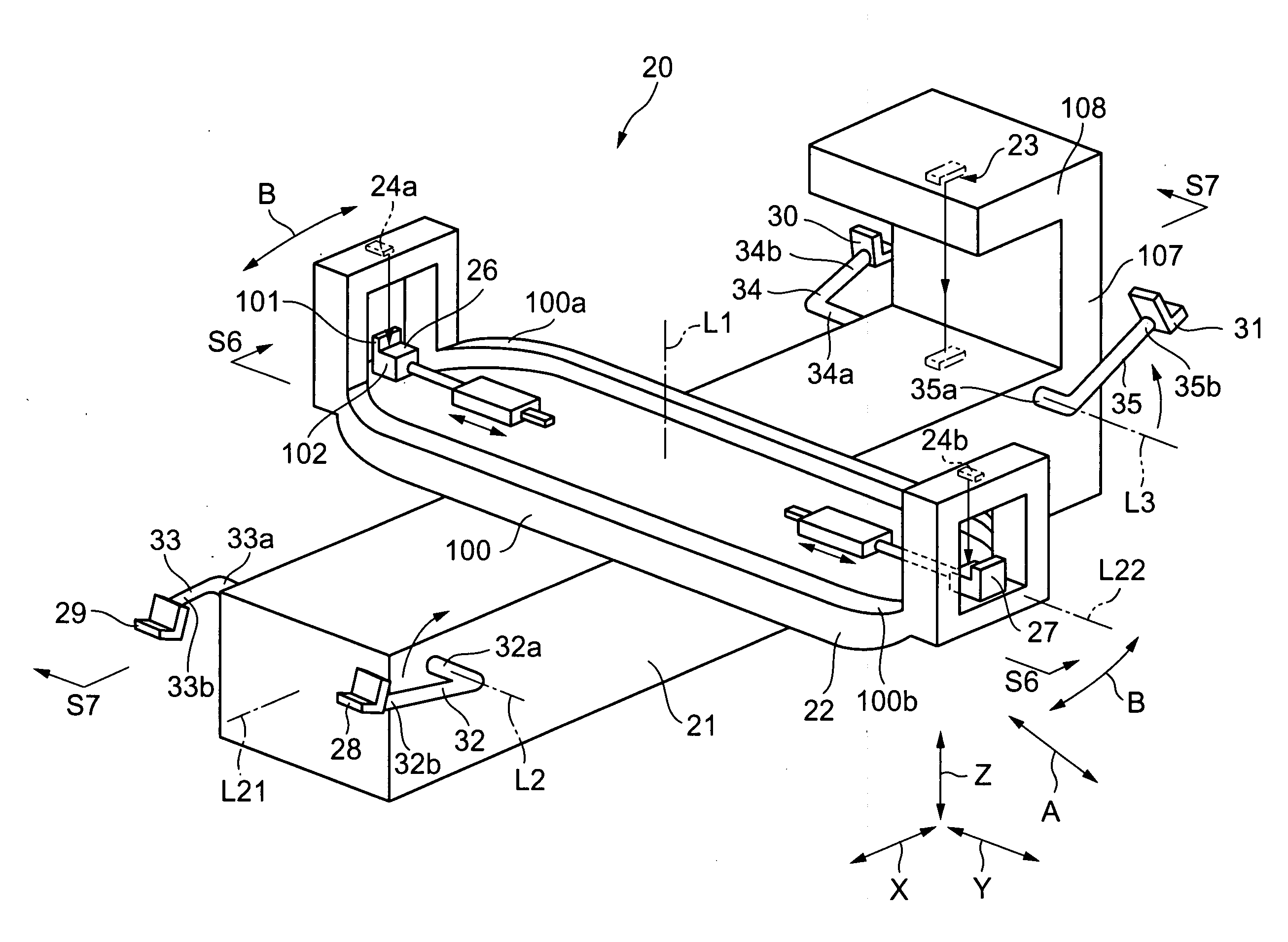
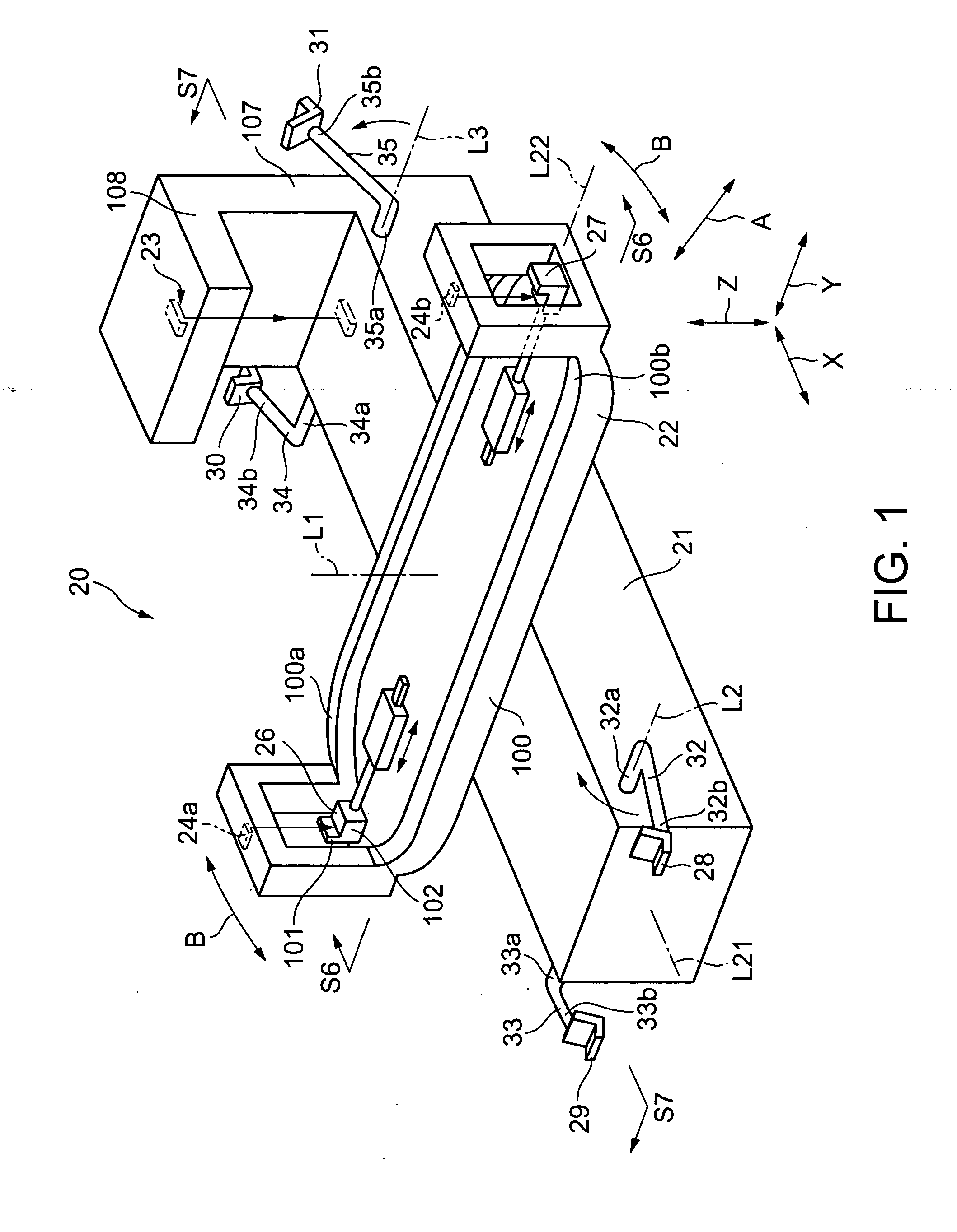
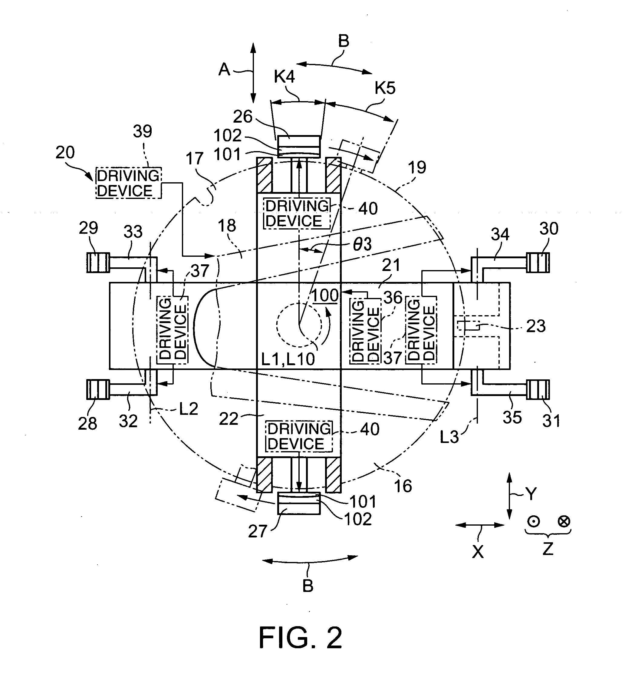
[0097]FIG. 1 is a typical perspective view of an edge-holding aligner 20 in a preferred embodiment according to the present invention and FIG. 2 is a plan view with certain parts omitted of the edge-holding aligner 20. In some of the accompanying drawings some parts are omitted or simplified to facilitate understanding.

[0098] An edge-holding aligner 20 (hereinafter, referred to simply as “aligner 20”) determines the angular position of a notch 17 formed in the edge 16 of a semiconductor wafer 19 and adjusts the position of the wafer 19 on the basis of the angular position of the notch 17. The notch 17 is an orientation indicator for use in adjusting the position of the wafer 19. The notch 17 is a V-shaped cut in the edge of the wafer 19.

[0099] The wafer 19 is carried to the aligner 20 by a robot hand 18, namely, a substrate carrying device. The robot hand 18 comes into contact with the wafer 19 from below the wafer 19 to support the wafer 19 thereof for carrying. The robot hand 18...


PUM


Abstract

The angular position of a notch 17 is determined on the basis of data provided by second notch detectors 24a and 24b and an encoder 25. A controller 38 turns a rotational arm 22 for angular displacement such that holders 26 and 27 are displaced in a circumferential direction B from the notch 17, and then the holders 26 and 27 hold a wafer 19. Since the holders 26 and 27 are in touch with edges in which the notch 17 is not formed, the first notch detector 23 is able to detect the notch 17 without difficulty. Thus the position of the wafer 19 relative to the rotational arm 22 does not need to be changed several times depending on positions at which the holders 26 and 27 hold the wafer 19, which is necessary in the prior technology. The aligner 20 touches parts, not including the notch 17, of the wafer 19 and is capable of adjusting the position of the wafer 19 in a short time.

Description

BACKGROUND OF THE INVENTION [0001] 1. Field of the Invention [0002] The present invention relates to an edge-holding aligner capable of holding an edge of a substrate and turning the substrate to adjust the position of the substrate. [0003] 2. Description of the Related Art [0004] A disk-shaped substrate, such as a semiconductor wafer, has an orientation indicator, such as a notch or an orientation flat, for indicating a reference position in a circumferential direction. The notch is a V-shaped indentation cut in the edge of the substrate. The orientation flat is a chord formed by cutting a segment from a peripheral part of the substrate. [0005] When the substrate is subjected to a surface treatment, such as when the semiconductor wafer is subjected to a gate forming process, the substrate needs to be set on a processing stage with the angular position of its orientation indicator coincided with a predetermined reference angular position. [0006] Generally, a plurality of substrates ...

Claims


Application Information

Patent Timeline
Patent Type & Authority Applications(United States)
IPC IPC(8): H01L21/68G03B27/58
CPCG03B27/58H01L21/68
Inventor HASHIMOTO, YASUHIKOHIROOKA, YASUOYAMAGUCHI, TAKAOKANDA, HIROSHI
Owner KAWASAKI HEAVY IND LTD
Why Eureka
Try Eureka