

Image forming method, image forming apparatus, and program
- Summary
- Abstract
- Description
- Claims
- Application Information
AI Technical Summary
Benefits of technology
Problems solved by technology
Method used
Image

Examples
first example
(FIRST EXAMPLE)
[0051] An example of history information processing in an image processing system using the LBP explained in the above embodiment will be explained next with reference to FIGS. 4 to 10.
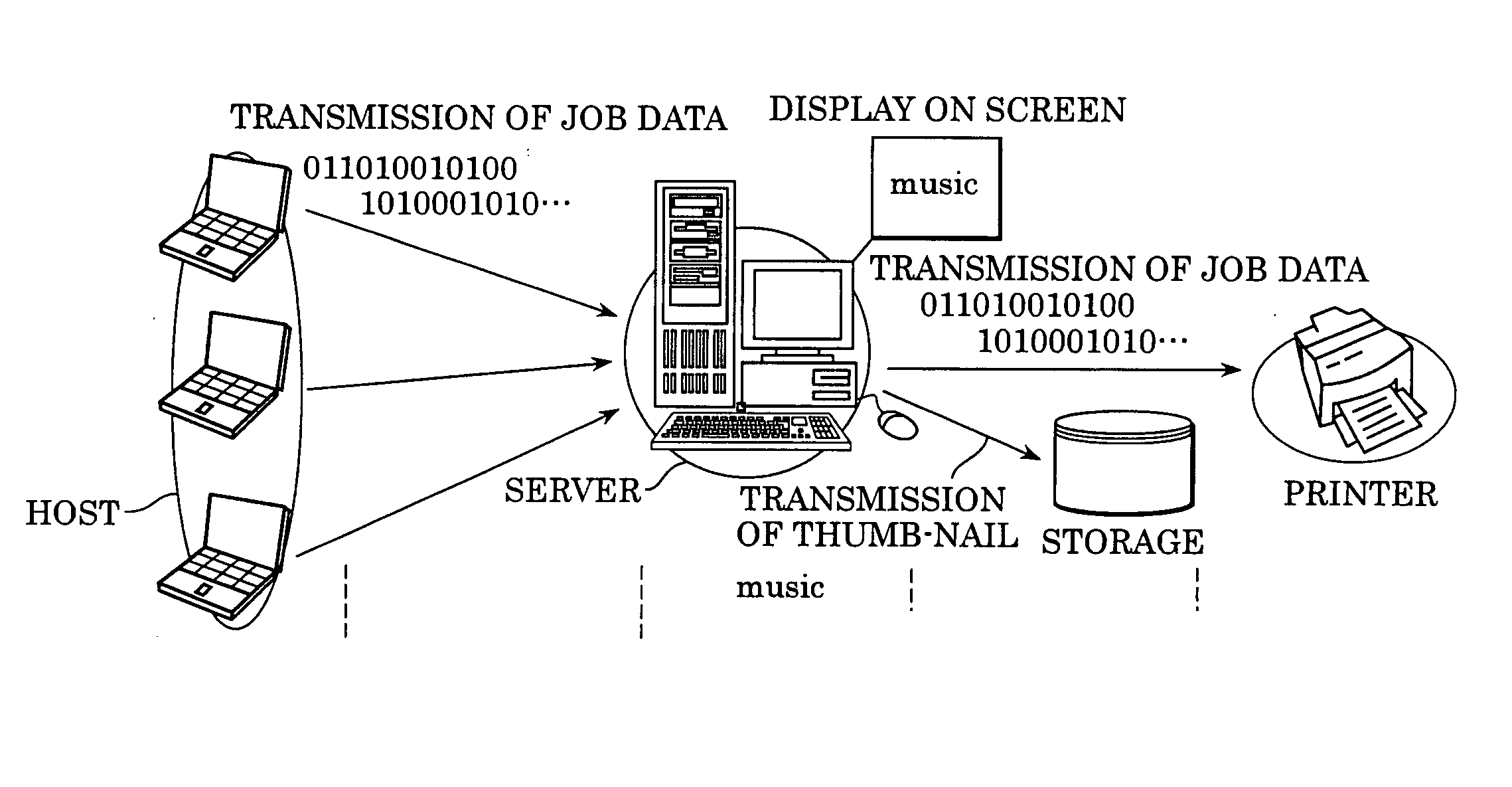
[0052]FIG. 4 illustrated an example of the device arrangement of the image processing system. FIG. 5 illustrates an example of an image of history information acquisition processing in the respective devices of the image processing system, wherein (a) to (d) show the contents of processing executed by the respective devices. FIG. 6 is a flowchart showing an example of an overall processing flow of history information management processing executed by a history information management device, wherein 6-a to 6-i show respective steps. FIG. 7 is a flowchart showing an example of a history information acquisition preparation processing flow executed in the history information management processing, wherein 7-a to 7-k show respective steps. FIG. 8 is a flowchart showing an example of a histo...
second example
(SECOND EXAMPLE)
[0067] An example of a case that an image processing apparatus control code, which uses, in particular, a page division region, is used in the history information management processing in the image processing system explained in the first example is explained next with reference to FIGS. 11 to 13.
[0068]FIG. 11 shows an example of the concept of duplicated text elimination processing executed in the history information acquisition processing in the respective devices of the image processing system, wherein (a) to (d) show the contents of processing executed by the respective devices. FIG. 12 shows an example of a history information acquisition preparation processing flow executed in the history information management processing, wherein 12-a to 12-q show respective steps. FIG. 13 shows an example of the concept of job search processing (job chasing).
[0069] First, an overview of the duplicated text elimination processing executed in the history information acquisiti...
third example
(THIRD EXAMPLE)
[0072] Examples of a user interface and text extraction processing when the history information management processing is executed in the image processing system using the LBP described in the above examples is described next with reference to FIGS. 14 to 16.
[0073]FIG. 14 shows an example of a history display presented by a history information management device to the user. FIG. 15 shows an example of the display presented by the history information management device to the user when the user executes job search processing. FIG. 16 shows an example of the concept of the text extraction processing.
[0074] An example of the history display presented to the user by the history information management device is described next with reference to FIG. 14. The history information management device causes job numbers to correspond to the contents of the histories of respective jobs and displays them on a screen. The contents of the histories to be displayed are text information...
PUM
 Abstract
Description
Claims
Application Information