Disk array optimizing the drive operation time

a technology of drive operation and disk array, applied in the direction of memory address/allocation/relocation, digital signal error detection/correction, instruments, etc., can solve the problems of shortening the operation period of disk devices, shortening the total active time of disk arrays, and affecting the performance of disk arrays, so as to shorten the total active time , the effect of increasing the capacity of the disk array

Inactive Publication Date: 2005-05-26
HITACHI LTD
View PDF55 Cites 78 Cited by
  • Summary
  • Abstract
  • Description
  • Claims
  • Application Information

AI Technical Summary

Benefits of technology

[0003] Some disk devices used for a disk array may shorten a total active time when they are turned on 24 hours a day in comparison to a case where the disk devices are turned on only when needed. The total active time, signifies the accumulated time during which the disk device is turned on. Such problem caused by deterioration and wear of parts constituting the disk devices. The disk device's total active time shortens when the disk device is turned on 24 hours a day and is operated continuously 24 hours a day. As a result, the disk device's operation period shortens. Such disk device is not suited for 24-hour continuous operations. The disk array capacity increases year after year. There is a trend of increasing the number of disk devices to be mounted. The power consumption for disk arrays tends to increase.

Problems solved by technology

Some disk devices used for a disk array may shorten a total active time when they are turned on 24 hours a day in comparison to a case where the disk devices are turned on only when needed.
Such problem caused by deterioration and wear of parts constituting the disk devices.
As a result, the disk device's operation period shortens.
Such disk device is not suited for 24-hour continuous operations.
The power consumption for disk arrays tends to increase.

Method used


Image

  • Disk array optimizing the drive operation time
  • Disk array optimizing the drive operation time
  • Disk array optimizing the drive operation time

Examples


first embodiment

[0018] The first embodiment will now be described.

[0019] (1) Description of the System Configuration

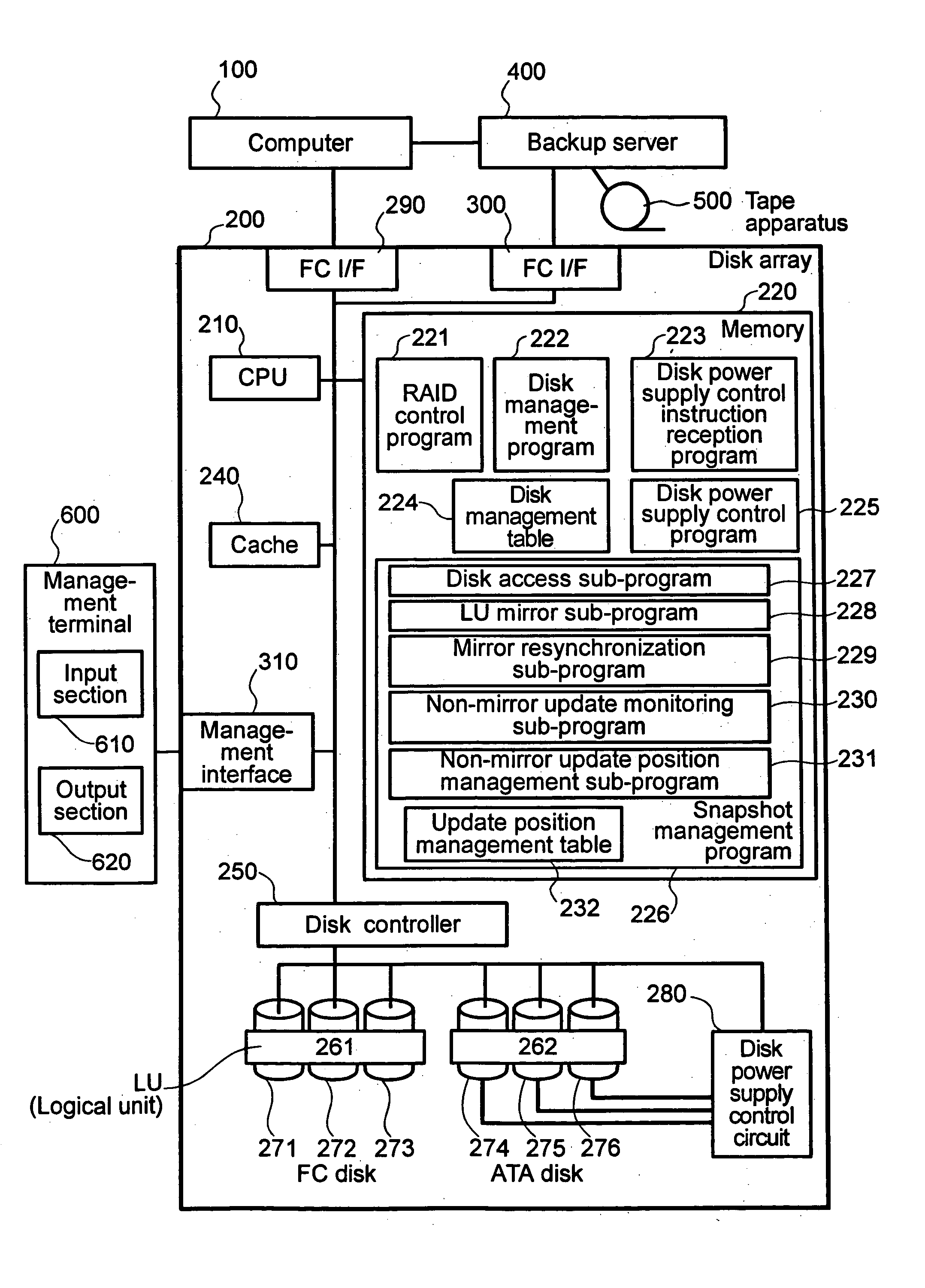
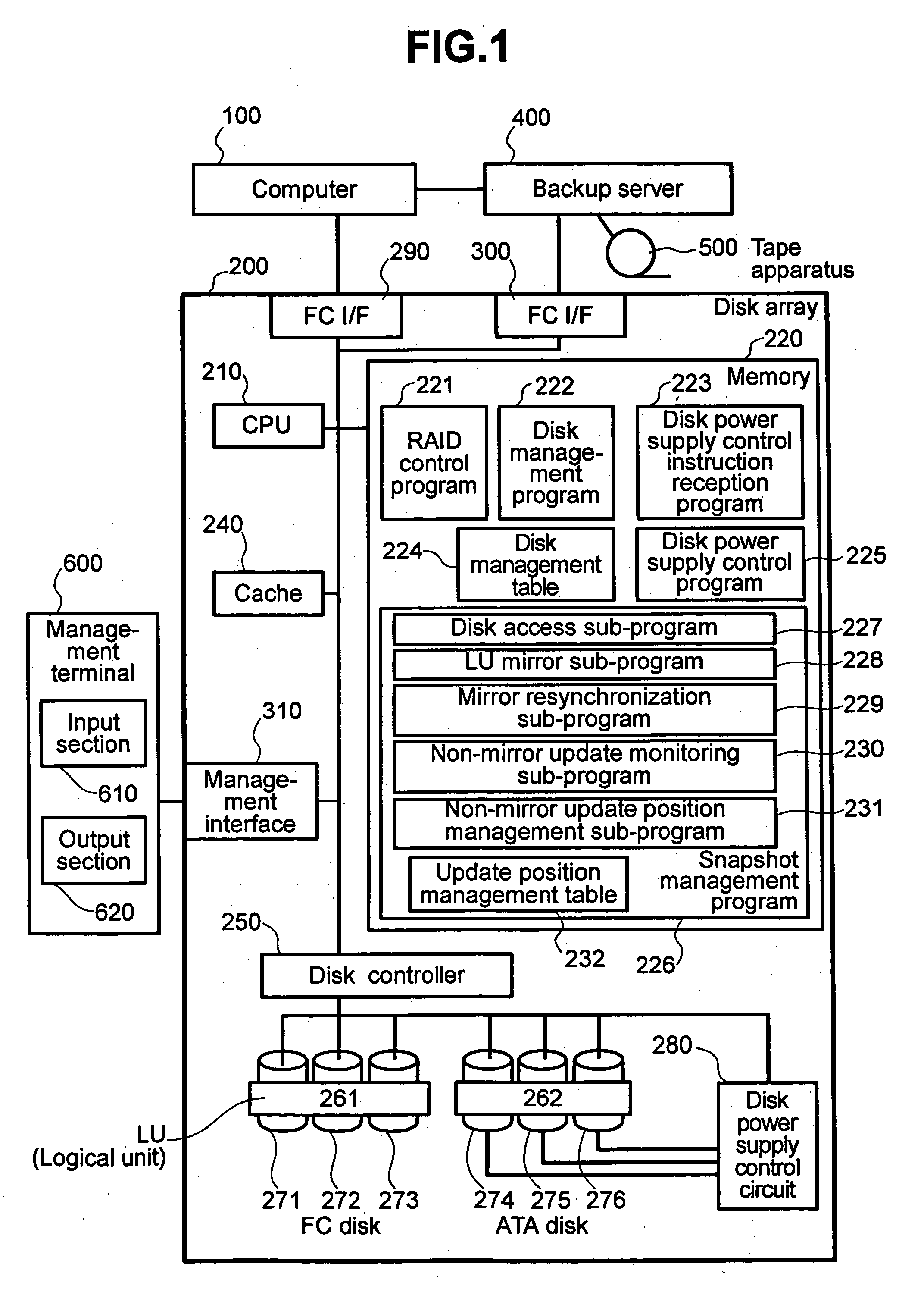
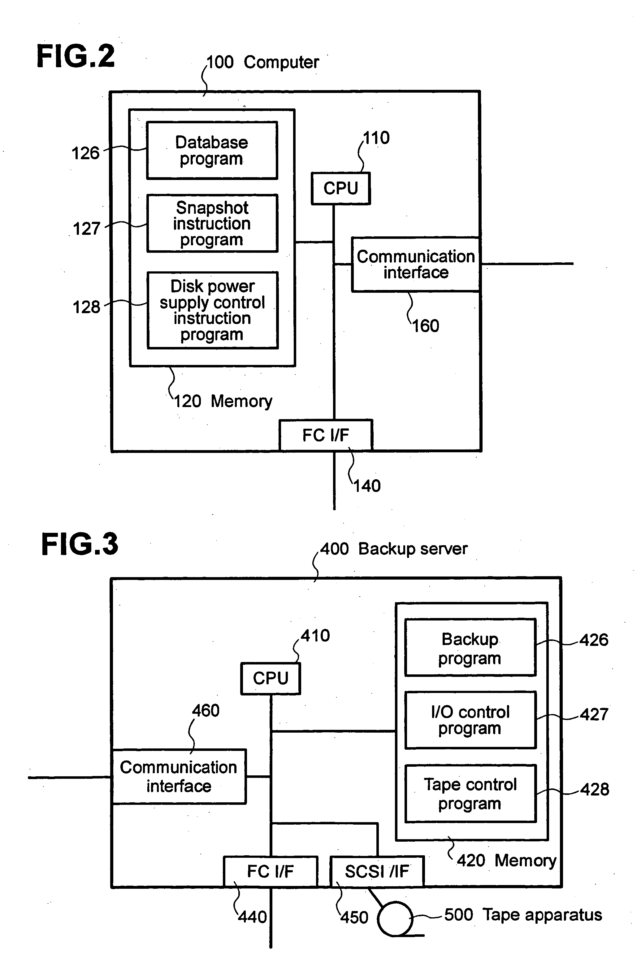
[0020]FIG. 1 shows an example of the system configuration according to the first embodiment. In FIG. 1, a computer 100 is connected to a disk array 200 via a Fibre Channel interface (hereafter referred to as an FC I / F) 290 of the disk array 200. A backup server 400 is connected to the disk array 200 via an FC I / F 300 of the disk array 200. A tape apparatus 500 is connected to the backup server 400. A management terminal 600 is connected to the disk array 200 via a management I / F 310 of the disk array 200.

[0021] The disk array 200 comprises a CPU 210, memory 220, a cache 240, and a disk controller 250. The CPU 210 controls the disk array 200. The cache 240 stores user data of the disk array 200. The disk controller 250 controls a plurality of disk devices.

[0022] The disk controller 250 is connected to a plurality of FC disks 271 through 273 (hereafter referred to as an FC disk grou...

second embodiment

[0067] The second embodiment will now be described.

[0068] (1) Description of the System Configuration

[0069]FIG. 8 shows an example of the system configuration according to the second embodiment. The following describes only differences from the first embodiment. Unlike the example in FIG. 1, the system in FIG. 8 uses entirely ATA disks 281 through 289 connected to the disk controller 250. The computer 100 accesses a storage area in the ATA disks 281 through 283 as a SCSI LU. Likewise, the computer 100 accesses a storage area in the ATA disks 284 through 286 as another SCSI LU. The computer 100 accesses a storage area in the ATA disks 287 through 289 as yet another SCSI LU. The LU in the ATA disks 281 through 283 is defined as an LU 263. The LU in the ATA disks 284 through 286 is defined as an LU 264. The LU in the ATA disks 287 through 289 is defined as an LU 265. FIG. 8 shows that each of the LU 263, the LU 264, and the LU 265 constitutes a storage area extending to a plurality o...


PUM

PropertyMeasurementUnit
active timeaaaaaaaaaa
power consumptionaaaaaaaaaa
timeaaaaaaaaaa

Abstract

Some disk devices used for a disk array may shorten a total active time when they are turned on 24 hours a day in comparison to a case where the disk devices are turned on only when needed. The disk device's total active time shortens when the disk device is turned on 24 hours a day and is operated continuously 24 hours a day. As a result, the disk device's operation period shortens. Such disk device is not suited for 24-hour continuous operations. The disk array capacity increases year after year. There is a trend of increasing the number of disk devices to be mounted. The power consumption for disk arrays tends to increase. A computer accessing a disk array has a disk control instruction program which allows the disk array to turn on or off specific disk devices in it. The disk array has a disk power supply control instruction reception program and a disk power supply control circuit. The disk power supply control instruction reception program receives an instruction to turn on or off disk devices from the computer. The disk power supply control circuit turns on or off a disk device corresponding to an LU specified by the computer.

Description

BACKGROUND OF THE INVENTION [0001] The present invention relates to an external storage device system. More specifically, the present invention relates to a technology for prolonging an operation period of a disk device (hereafter also referred to simply as a disk) and decreasing power consumption of a storage device system (hereafter referred to as a disk array). Here, the disk device's operation period signifies a period from the time to start using the disk device to the time when the disk device becomes unusable. [0002] A disk array is a type of storage device systems connected to a computer. The disk array is also referred to as a RAID (Redundant Arrays of Inexpensive Disks) and constitutes a storage device system comprising a plurality of disk devices arranged in an array and a control section to control them. The disk array concurrently operates disk devices to accelerate read requests (requests to read data) and write requests (requests to write data) and to provide data wit...

Claims


Application Information

Patent Timeline
Patent Type & Authority Applications(United States)
IPC IPC(8): G06F3/06G06F1/32G06F11/10G06F12/02G06F12/08G06F13/10G11B20/18G11C11/22
CPCG06F3/0616G06F3/0625Y02B60/1246G06F3/0689G06F3/0634Y02D10/00
Inventor YAGISAWA, IKUYAMATSUNAMI, NAOTOMANNEN, AKIHIROTAKAMOTO, KENICHI
Owner HITACHI LTD
Why Eureka
Try Eureka