
Method for controlling a DC-to-DC converter

a technology of dc-to-dc converter and control method, which is applied in the direction of dc-dc conversion, power conversion system, instruments, etc., can solve the problems of reducing the efficiency of the converter to an unacceptable level, complicating the design of the converter, and often requiring a trade-off between stability and control system, so as to reduce the active time of pulses and reduce output voltage

Active Publication Date: 2017-02-28
ROHM CO LTD
View PDF20 Cites 0 Cited by
  • Summary
  • Abstract
  • Description
  • Claims
  • Application Information

AI Technical Summary

Benefits of technology

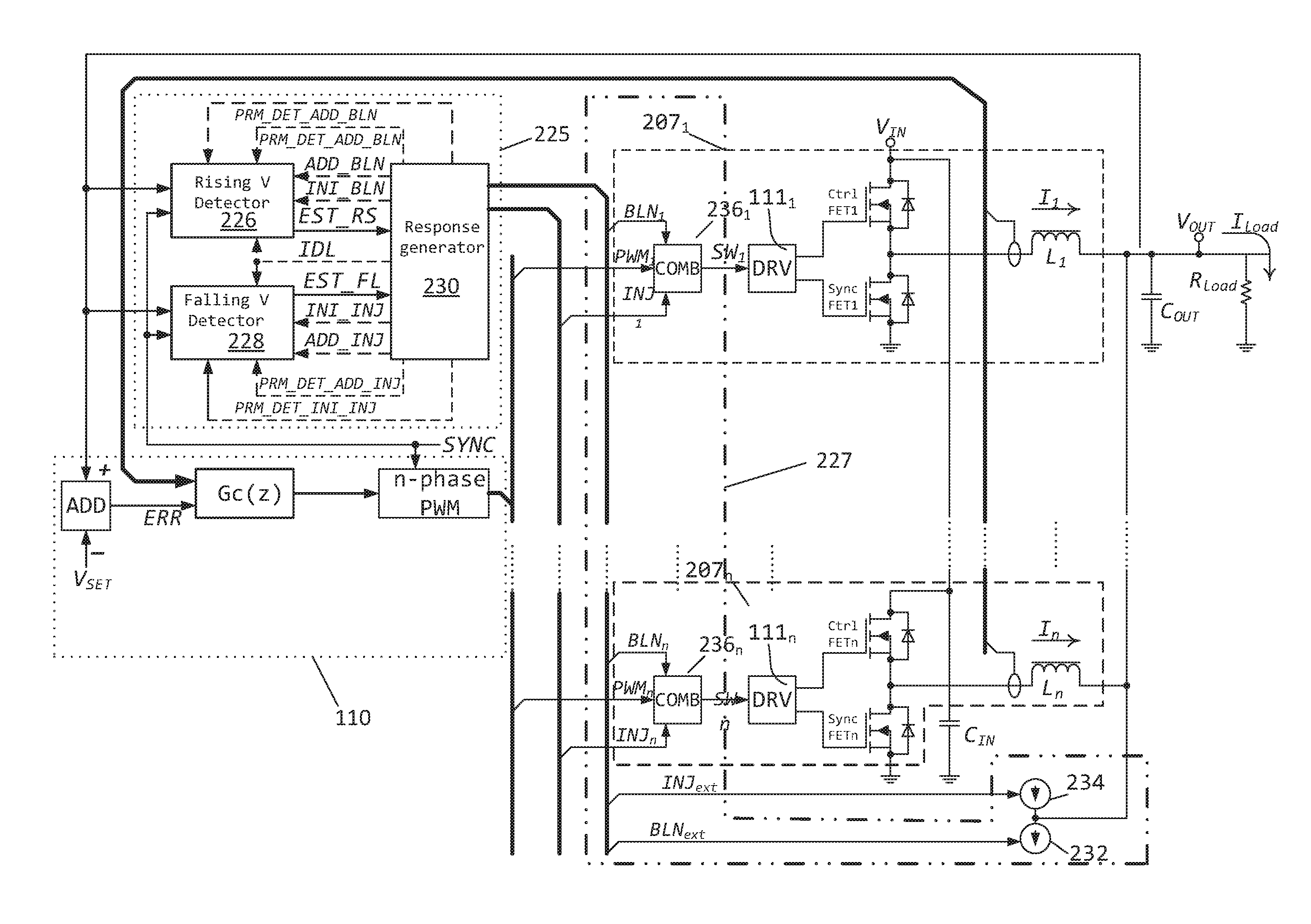
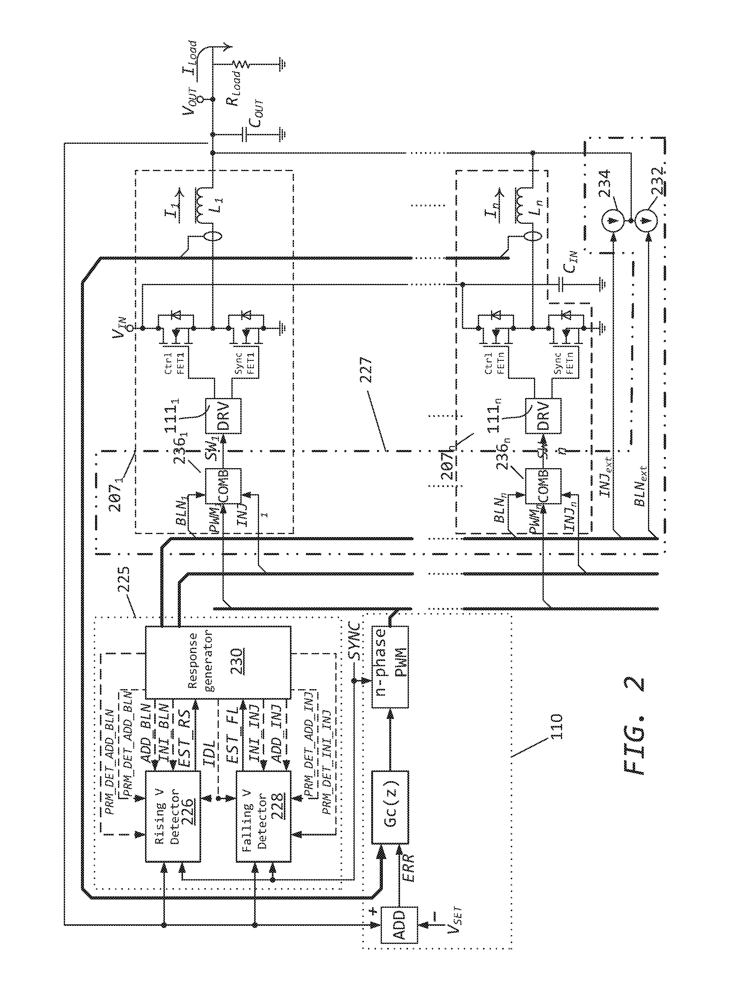
[0027]In a further aspect, a controller is provided for minimizing the output voltage deviation of a DC-DC converter in reaction to a load current step. The controller comprising: a detector for detecting a load current step to a new load comprising of an measurer or estimator of a voltage change at the output voltage rail of the DC-DC converter; a selector of parameters of a response to compensate a voltage change; a response generator for generating a response with the selected parameters; a combiner for combining the generated response with signals of the DC-DC converter. The measurer or estimator suitably includes a delay line and a plurality of difference calculators. The combiner suitably combines the generated response with a pulse width modulated signal in the DC-DC converter.
[0029]The controller may comprise a detector for detecting a negative load current step to a new load current load comprising of an measurer or estimator of a positive voltage change at the output voltage rail of the DC-DC converter; a selector of parameters of a response to decrease output voltage; a response generator for generating a response with the selected parameters and means for applying the generated response to the components of the a DC-DC converter. The means for applying a response may comprise a controlled current sink or a combiner for reducing active time of the pulses with modulated width.

Problems solved by technology

This is difficult because the nature of microprocessor loads is that they produce fast load transients.
However, such feedback control systems often require a trade-off between stability and transient response.
However, increasing the switching frequency complicates the design of the converter, and as the switching frequency increases, the efficiency of the converter decreases eventually to an unacceptable level.
However, such a reduction results in an increase in output voltage ripple.
In addition, a larger ripple current through the filter inductor will result in a larger RMS current through the power switches of the converter, which will reduce the overall efficiency of the converter under steady state operation.
However deviations in the supply voltage can be inacceptable in some applications.
However, this strategy requires a very large output capacitor (e.g., 5,000 to 10,000 uF), which is bulky and expensive, and as a result is generally not considered practical.
Unfortunately, this solution does not provide a fast enough response as demanded in modern microprocessor applications.
Additionally, changing the loop filter parameters of a control system can lead to unstable behaviour.
The size of the window determines the performance of the transient suppression system having the window too small results in noise and ripple triggering the suppression action unnecessarily and having the window larger delays detection in the output voltage.
This approach in most of the practical cases leads to instable operation of the power converter due to the significant delay between a pulse injected at the input of the LC filter of the power stage and an output voltage response to the pulse which is observed at the output of the LC filter.
In practice the application range of this solution is limited to multiphase power converters.
Also the performance of this system is compromised due to the fact that when the output voltage starts stewing, the system generates the first pulse only for a single phase right after the first threshold level is crossed.
This results in a delay in the adequate response to a big step in load current.
In practice the noisy environment of the high current switching DC-to-DC converter and / or fast nonlinear changes of the load current lead to incorrect estimations of the valley point voltage and time offset.
As a result, these factors of uncertainty give incorrect values for the pulsewidths of the injected and blanking pulses.
This in turn leads to degradation of performance and in some practical cases might give even worse undershoots / overshoots at the output voltage than there might be without using the described approach.

Method used


Image

  • Method for controlling a DC-to-DC converter
  • Method for controlling a DC-to-DC converter
  • Method for controlling a DC-to-DC converter

Examples


second embodiment

[0148]This second embodiment of the slew rate detector 460 provides capability for generating corresponding threshold waveforms for the steady state operation of the power converter and for the different intervals of a transient response sequence. This capability allows robust detection of the output voltage slewing, accurate run time adjustment of the duration of the initial pulse and modification of the succession of the follow-up constant-on-time pulses.

[0149]FIG. 5 is a block diagram that depicts an example embodiment 560 of the slew rate detector which processes output voltage VOUT at its “voltage” input and provides raw estimates of the slew rate at its output. This embodiment of the slew rate detector has the improved transient detection performance by having the capability for the runtime adjustment of the thresholds for the steady state ripple. This allows for adjustment over time to account for example to changes in operating conditions, e.g. temperature or ageing of compo...

first embodiment

[0180]The selector of the blanking sequence parameters 883 and selector of the injection sequence parameters 882 suitably have similar structures and will now be explained with reference to a first embodiment for a sequence parameter selector as shown in FIG. 9

[0181]The sequence parameter detector detects the start of the transient on the output voltage VOUT on the basis of the joint processing of the succession of raw estimations of the slew rate from the rising voltage detector 226 and falling voltage detector 228. If a transient is detected, then the selector of the sequence parameters provides at its outputs initial parameters of the transient mitigation response and thresholds for the rising voltage detector 226 and falling voltage detector 228 (as employed in FIG. 4, 5) for different intervals of the transient mitigation response.

[0182]The sequence parameter detector accepts as an input an m+1 bit binary word, which represents raw estimation of the slew rate. This input is app...


PUM


Abstract

Methods and circuits for power supply arrangement and control are disclosed herein. More specifically the application relates to a control method and a controller for a DC-to-DC converter, such as a synchronous Buck converter, which implements a transient detection scheme together with response generation to allow the converter to recover from a positive and / or negative load current step in the robust way, with low undershoot / overshoot at the output voltage. The control method may be implemented by either an analog or a digital circuit. The controller may be integrated with existing controller schemes (such as voltage-mode controllers) to provide superior dynamic performance during large-signal transient conditions while providing stable operation during steady state conditions. The methods and circuits provided herein are applicable to Buck converters and Buck-derived converters such as forward, push-pull, half-bridge, and full-bridge converters.

Description

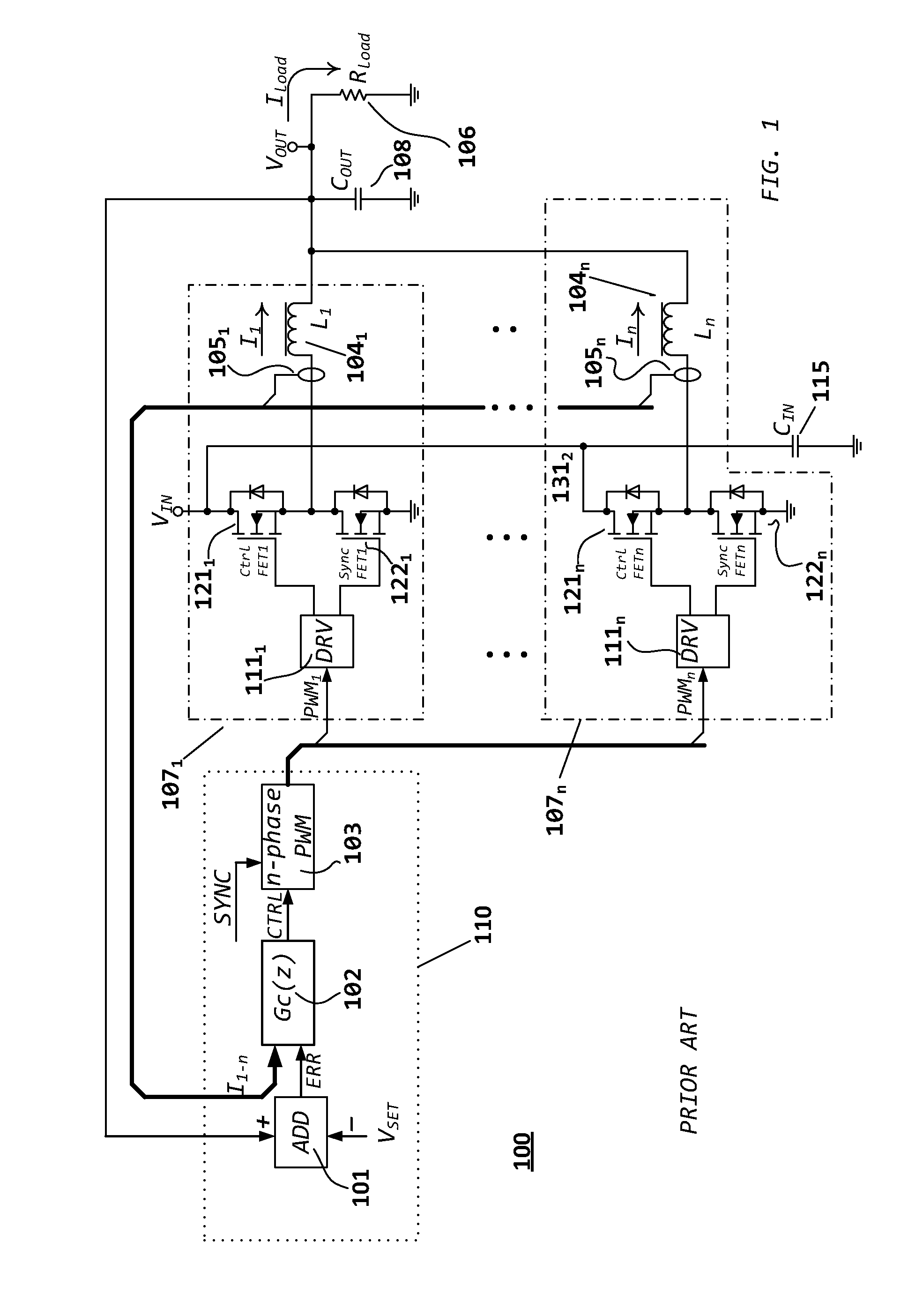
FIELD OF THE APPLICATION[0001]This application relates, in general, to regulator circuits and, more particularly, to switching DC-to-DC converters.BACKGROUND OF THE APPLICATION[0002]The present application relates to a correction circuit for improving feed forward or feedback regulation in switched power supplies. In particular, to switching power supplies suitable for driving a load where a load current may abruptly vary.[0003]Switching electrical power supplies, also referred to as switched mode power supplies, are capable of efficiently converting an input voltage to an output voltage. One or more active power devices or “phases” are switched, that is, turned on and turned off in rapid succession, to control the average amount of energy that is driven from the input to an energy storage element at the output. This switching is controlled in a manner that results in a controlled voltage waveform at the output. For example, a step down converter, such as a buck converter, converts ...

Claims


Application Information

Patent Timeline
Patent Type & Authority Patents(United States)
IPC IPC(8): H02M3/158H02M3/156
CPCH02M3/158H02M3/156H02M2003/1566H02M3/1566
Inventor KELIN, TIMURRYAN, JOHNO'SHEA, CORMAC
Owner ROHM CO LTD
Learn More