Automated method and system for the evaluation of disease and registration accuracy in the subtraction of temporally sequential medical images

Inactive Publication Date: 2005-05-26
CHICAGO UNIV OF
View PDF26 Cites 67 Cited by
  • Summary
  • Abstract
  • Description
  • Claims
  • Application Information

AI Technical Summary

Benefits of technology

[0049] An object of the present invention is a method for detection of pathological changes characterized by goo

Problems solved by technology

A radiologist might have adequate experience interpreting temporal subtraction images, or might feel burdened by the need to review an additional image during a demanding clinical schedule.
Moreover, the quality of image registration may not be consistent across all pairs of temporal subtraction images.
As a result of poor registration, the clinical utility of certain temporal subtraction images may be limited.
However, these conventional methods do not automatically identify a best fit pair based on registration parameters, thus requiring a radiologist to look at all subtraction imag

Method used


Image

  • Automated method and system for the evaluation of disease and registration accuracy in the subtraction of temporally sequential medical images
  • Automated method and system for the evaluation of disease and registration accuracy in the subtraction of temporally sequential medical images
  • Automated method and system for the evaluation of disease and registration accuracy in the subtraction of temporally sequential medical images

Examples


Example

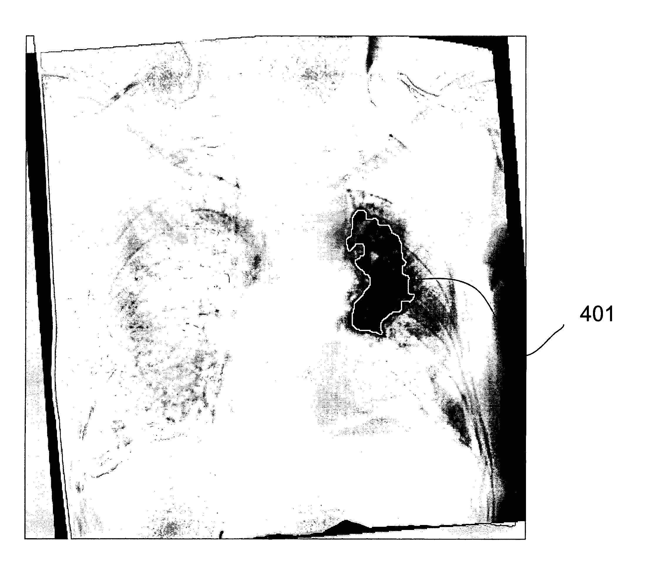
[0073] Thus, the method of the first embodiment is summarized in FIG. 8. The method begins with obtaining a temporal subtraction image (S601). This temporal subtraction image is than subjected to a lung mask to extract a lung mask region (S602). The extracted lung mask region is then subjected to spatial smoothing (S603). The spatially smoothed data is then used to construct a gray level histogram (S604). Histogram statistics are then computed (S605). These histogram statistics are used to determine registration accuracy (S699) as well as to select gray level threshold information (S605). From the gray level threshold information, a binary image is constructed (S606). Within the constructed binary image, contiguous regions of “ON” pixels are identified so as to identify regions of interest (S607). Within these regions of interest, geometric and gray level features are extracted (S608). The extracted geometric and gray level features may also be used to determine registration accurac...

Example

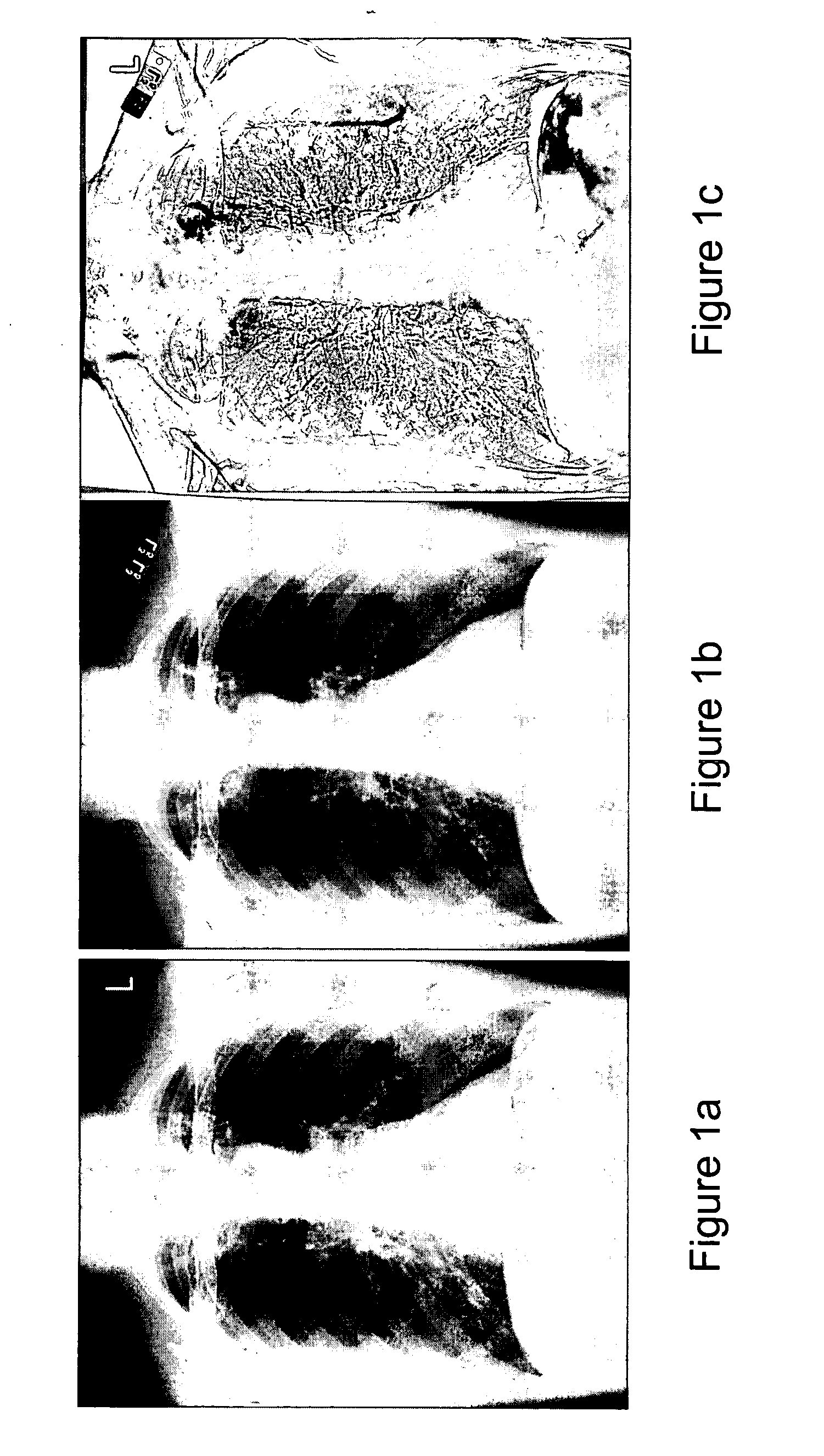
[0081] The method of the second embodiment is summarized in FIG. 9. Dual energy images are obtained at separate times (S701A, S701B). Each dual energy acquisition results in a standard image (S701A1, S701B1), a soft tissue image (S701A3, S701B3), and a bone image (S701A2, S701B2). The standard images obtained from the two dual energy acquisition steps are then subjected to temporal subtraction (S702), from which temporal subtraction parameters are obtained (S703). These temporal subtraction parameters are then used in a corresponding soft tissue temporal subtraction (S704A) and / or a bone temporal subtraction (S704B) process. The soft tissue temporal subtraction (S704A) is exercised against the soft tissue images obtained from the two dual energy acquisitions (S701A3, S701B3). Similarly, the bone temporal subtraction process (S704B) is exercised against the bone images obtained from the two dual energy acquisitions (S701A2, S701B2). The soft tissue temporal subtraction data and / or bo...


PUM


Abstract

An apparatus, method and computer program product for performing computer aided diagnosis on temporal subtraction images of objects. A mode of a gray-level histogram is identified, and a gray-level threshold is established at a predefined fraction of this modal value. All pixels with gray levels below this threshold that lie within the lung regions of the temporal subtraction image remain “on,” while all other pixels are set to zero. Area and circularity requirements are imposed to eliminate false-positive regions. Areas of pathologic change identified in this manner may be presented as outlines in the subtraction image or as highlighted regions in the original radiographic image so that, in effect, temporal subtraction becomes a “background” process for computer-aided diagnosis. The present invention is also directed to method, apparatus, and computer program product for performing temporal subtraction on energy subtraction images, with or without subsequent computer aided diagnosis, of objects.

Description

[0001] The present invention was made in part with U.S. Government support under USPHS grant USPHS EB00341. The U.S. Government may have certain rights to this invention.BACKGROUND OF THE INVENTION [0002] Field of the Invention [0003] A method, system, and computer program product for computer aided detection (CAD) of disease with a reduced false positive rate. [0004] The present invention also generally relates to computerized techniques for automated analysis of digital images, for example, as disclosed in one or more of U.S. Pat. Nos. 4,839,807; 4,841,555; 4,851,984; 4,875,165; 4,907,156; 4,918,534; 5,072,384; 5,133,020; 5,150,292; 5,224,177; 5,289,374; 5,319,549; 5,343,390; 5,359,513; 5,452,367; 5,463,548; 5,537,485; 5,598,481; 5,622,171; 5,638,458; 5,657,362; 5,666,434; 5,668,888; 5,740,268; 5,832,103; 5,873,824; 5,881,124; 5,931,780; 5,974,165; 5,982,915; 5,984,870; 5,987,345; 6,011,862; 6,058,322; 6,067,373; 6,075,878; 6,078,680; 6,088,473; 6,112,112; 6,138,045; 6,141,437; 6,...

Claims


Application Information

Patent Timeline
IPC IPC(8): G06FG06K9/00G06T5/50G06T7/00
CPCA61B6/463A61B6/482G06T2207/30061G06T7/0012G06T7/0024G06T5/50G06T7/30
Inventor MACMAHON, HEBERARMATO, SAMUEL G. III
Owner CHICAGO UNIV OF
Why Eureka
Try Eureka