Surface scan measuring device and method of forming compensation table for scanning probe

a technology of scanning probe and measuring device, which is applied in the direction of mechanical measuring arrangement, instruments, and using mechanical means, etc., can solve the problems of measurement errors, insufficient correction of detection errors, raised errors in detecting displacement of stylus, etc., and achieve high accuracy.

Active Publication Date: 2005-05-26
MITUTOYO CORP
View PDF11 Cites 28 Cited by
  • Summary
  • Abstract
  • Description
  • Claims
  • Application Information

AI Technical Summary

Benefits of technology

[0023] It is therefore an object of the present invention to overcome the above-mentioned drawbacks by providing a surface scan measuring device that can measure the surface

Problems solved by technology

There are raised errors in detecting displacements of the stylus 21 by the probe sensor.
Then, errors are brought about in the displacement amount, which leads to measurement errors.
However, in some cases, detection errors cannot be sufficiently corrected by only setting up the compensation coefficients Kxp′, Kyp′ and Kzp′ for the respective axes, and correcting output values of the probe sensor using the compensation coefficients.
Consequently, when measuring a perfect circle, the measurement result may come to an ellipse due to measurement errors.
That is, detection e

Method used


Image

  • Surface scan measuring device and method of forming compensation table for scanning probe
  • Surface scan measuring device and method of forming compensation table for scanning probe
  • Surface scan measuring device and method of forming compensation table for scanning probe

Examples


first embodiment

[0079] A first embodiment of the surface scan measuring device according to the present invention will be explained.

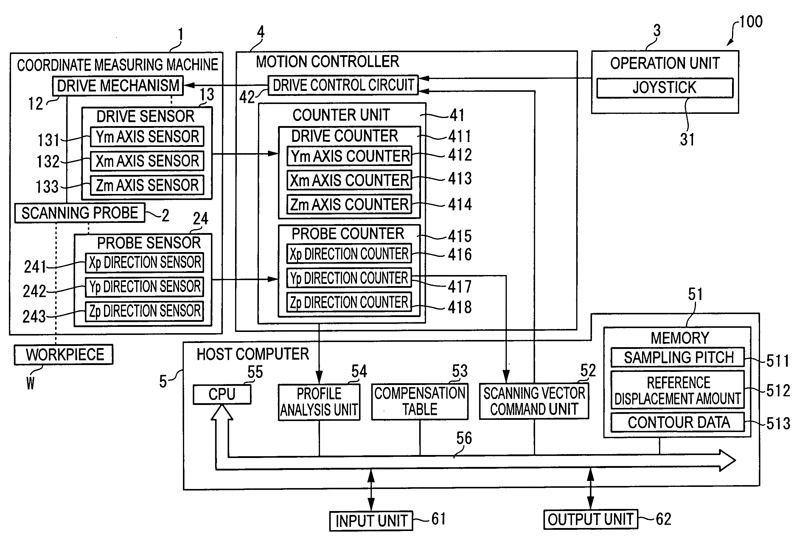
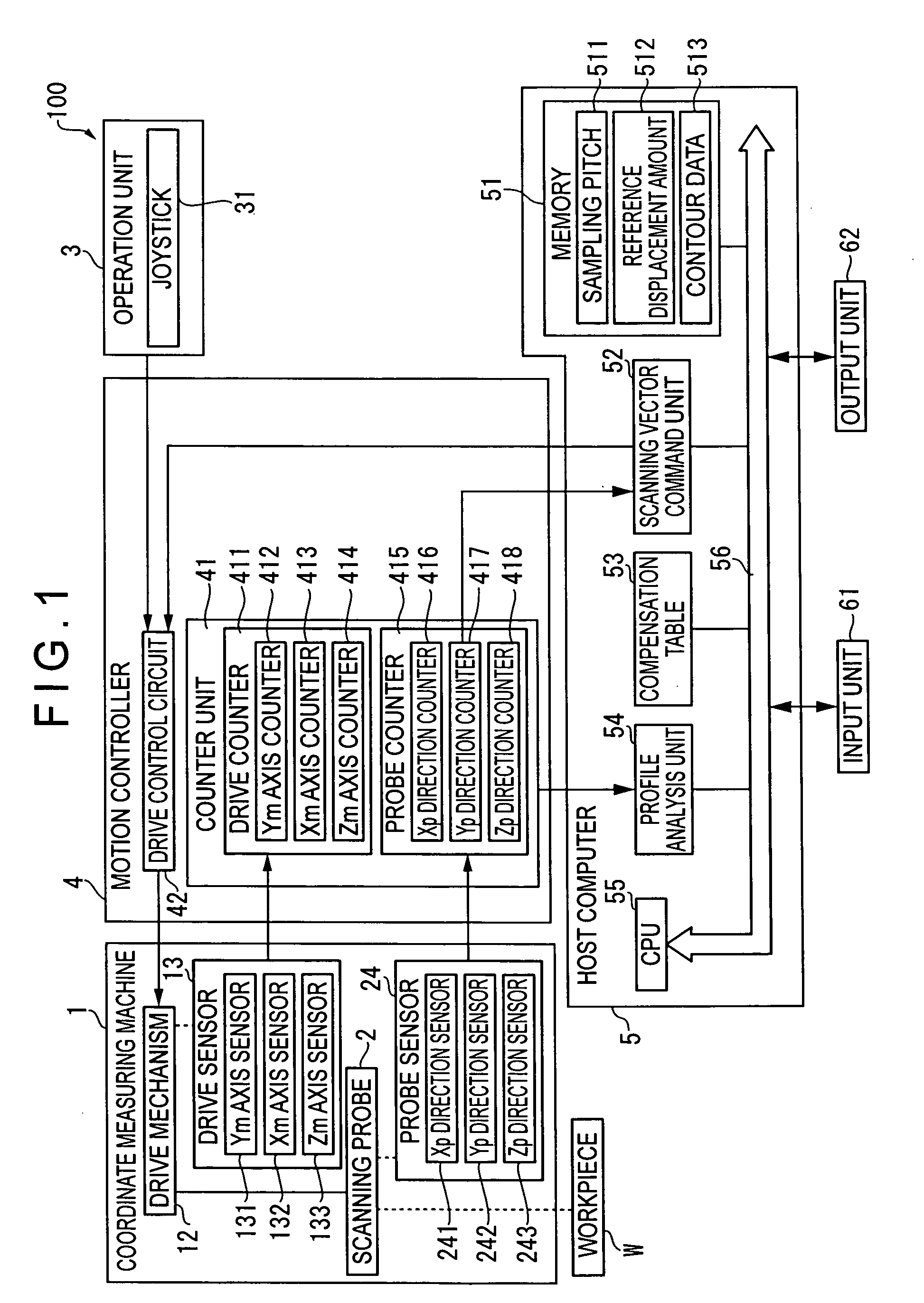
[0080]FIG. 17 shows a schematic view of a measuring system that is a surface scan measuring device using a scanning probe, while FIG. 1 shows a block diagram of a measuring system 100.

[0081] The measuring system 100, whose configuration is similar to that described in the description of related art, includes a coordinate measuring machine 1, an operation unit 3 for manually operating the coordinate measuring machine 1, a motion controller 4 for controlling and driving the coordinate measuring machine 1, a host computer 5 for issuing predetermined commands to the motion controller 4 and performing arithmetic processing such as profile analysis of a workpiece W, an input unit 61 for inputting measurement conditions etc., and an output unit 62 for outputting measurement results.

[0082] The coordinate measuring machine 1 has a measuring base 11, a drive mechanism (slide ...

second embodiment

[0139] A second embodiment of the method of forming a compensation table of a scanning probe according to the present invention will be explained. FIG. 4 shows a flow chart of the method of forming a compensation table.

[0140] Incidentally, in the second embodiment, a measuring system same to that described in the first embodiment can be used.

[0141] In ST1, a master ball 7 is prepared. The master ball 7 is a perfect sphere with a predetermined radius, and is arranged on, for example, the measuring base 11, as shown in FIG. 17.

[0142] In ST2, central coordinate value and radius of the master ball 7 are determined. In determining central coordinate value and radius of the master ball 7, for example, the master ball 7 may be measured at multiple points thereon using another scanning probe that has been calibrated in advance to determine the center and radius. Alternatively, the master ball 7 may be measured at multiple points thereon using a touch signal probe or a detector utilizing ...

third embodiment

[0164] A third embodiment of the surface scan measuring device according to the present invention will be explained.

[0165] Though the basic configuration of the third embodiment is similar to that of the first embodiment, and the configuration of compensation table is different, as shown in FIG. 7.

[0166] That is, a plurality of compensation tables 531, 532, . . . 53n are prepared, which correspond to a plurality of contact portions 22 and have compensation data stored therein.

[0167] For example, in the scanning probe 2, the stylus 21 may be composed of a linear axis unit and a cross-shaped arm perpendicular to the linear axis unit which has four arm members extending crisscross from the leading end of the linear axis unit, and the contact portion 22 is attached to the leading end of the respective arm members.

[0168] In this case, the compensation table is prepared for the respective contact portions (measuring pieces) 22, specifically, four compensation tables 531, 532, 533 and ...


PUM


Abstract

A measuring system includes a coordinate measuring machine for driving a scanning probe and a host computer. The host computer includes a compensation table (53) and a profile analysis unit (54). The compensation table stores, as compensation data, compensation coefficients to correct counter values of a probe counter (415), and compensation radiuses “r” to the workpiece surface concerning central coordinate values of a contact portion, for respective contact directions. The profile analysis unit has a contact direction calculation unit (542), a compensation data selection unit (543), a compensation calculation unit (544). The contact direction calculation unit calculates the contact direction along which the scanning probe comes into contact with a workpiece W, and the compensation data selection unit selects compensation data set up in the compensation table based on thus calculated contact direction.

Description

BACKGROUND OF THE INVENTION [0001] 1. Field of the Invention [0002] The present invention relates to a surface scan measuring device, and a method of forming a compensation table for a scanning probe. More particularly, the present invention relates to a surface scan measuring device that scans the surface of a workpiece to measure surface roughness, waviness, profile, etc. of the workpiece. [0003] 2. Description of Related Art [0004] There are diffused surface scan measuring devices that scan the surface of a workpiece to measure surface texture and three-dimensional profile of the workpiece, and there are known a machine for measuring surface roughness, a machine for measuring profile, a roundness measuring machine, and a coordinate measuring machine. [0005]FIG. 17 shows a schematic view of a conventional measuring system 100 that is a surface scan measuring device using a scanning probe. [0006] The measuring system 100 includes a coordinate measuring machine 1 for moving a scanni...

Claims


Application Information

Patent Timeline
IPC IPC(8): G01B5/012G01B5/20G01B21/04
CPCG01B21/045G01B5/20
Inventor NODA, TAKASHIOGURA, KATSUYUKI
Owner MITUTOYO CORP
Why Eureka
Try Eureka