Turbine blade airfoil having improved creep capability

a turbine blade and airfoil technology, which is applied in the direction of rotary propellers, machines/engines, rotary propellers, etc., can solve the problems of turbine blades that are not within the acceptable limits of manufacturers, blades to stretch, and known life-limiting factors of turbine blades, so as to prolong the exposure of material, increase the creep life of the blade, and reduce the mechanical load of the airfoil by the gases passing through the turbine

Active Publication Date: 2005-05-26
ANSALDO ENERGIA SWITZERLAND AG
View PDF3 Cites 54 Cited by
  • Summary
  • Abstract
  • Description
  • Claims
  • Application Information

AI Technical Summary

Benefits of technology

[0010] In an effort to increase the creep life of the blade, the mechanical loading on the airfoil by the gases passing through the turbine have been reduced. Creep life of a material is a function of the material properties, the stress level applied to the material, and extended exposure of the material to elevated temperatures. For cases where temperature of the material cannot be lowered, the creep life can be extended by lowering the mechanical load on the material, which for the present invention is accomplished by altering the aerodynamic shape of the airfoil.
[0011] It is an object of the present invention to provide a turbine blade having a novel airfoil geometry with lower mechanical load to the airfoil that results in increased creep life for a given operating temperature.

Problems solved by technology

A known life-limiting factor for a turbine blade is creep, which is plastic deformation of the blade caused by slippage along crystallographic directions in the individual crystals of the metallic blade.
This typically occurs when a turbine blade is exposed to high operating temperatures and a high stress level for an extended period of time, causing the blade to stretch.
Depending on the operating conditions, the turbine blade will eventually stretch or creep to a shape that is no longer within the manufacturers acceptable limits and must be replaced.
However, when attempting to enhance cooling, given a known amount of cooling air, new and more costly casting and manufacturing processes may be necessary in order to improve the cooling.

Method used


Image

  • Turbine blade airfoil having improved creep capability
  • Turbine blade airfoil having improved creep capability
  • Turbine blade airfoil having improved creep capability

Examples


Embodiment Construction

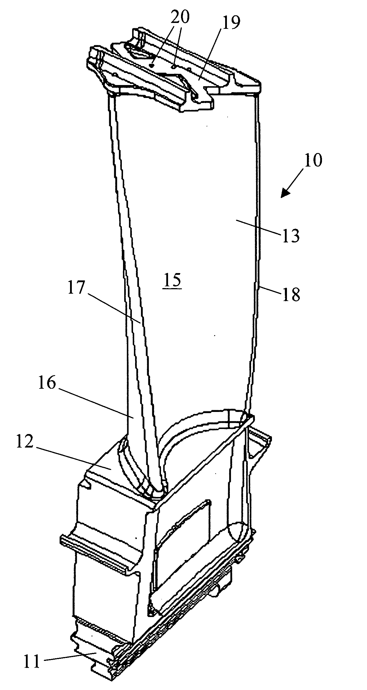
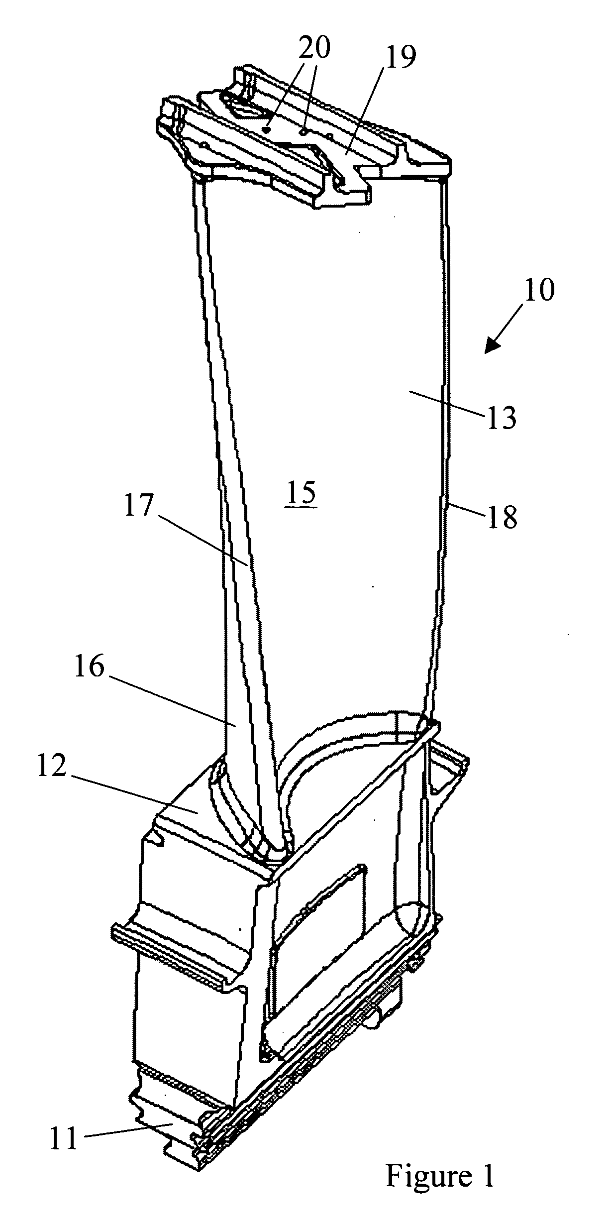
[0018] Referring to FIG. 1, a turbine blade 10 is shown in accordance with the present invention. Turbine blade 10 includes an attachment 11 and a platform 12 extending generally radially outward from attachment 11. An airfoil 13 extends generally radially outward from platform 12. Airfoil 13 has a compound curvature that includes a concave side 15 and a convex side 16 joined together at leading edge 17 and trailing edge 18. Extending generally radially outward from airfoil 13 is a shroud 19 that is used to dampen vibrations between adjacent turbine blades while also providing a seal to the outer gas path profile to prevent leakage of the hot combustion gases. Turbine blade 10 is cast from a nickel-based superalloy to provide superior resistance to the elevated temperatures of the hot combustion gases that drive the turbine.

[0019] To combat the elevated temperatures experienced by turbine blade 10, the blade is cooled by a plurality of generally radially extending holes 20 that ext...


PUM


Abstract

A turbine blade including an airfoil having a profile in accordance with Table 1 is disclosed. The turbine blade has a plurality of cooling passages extending radially outward through the airfoil. The aerodynamic profile of the airfoil has been reconfigured to reduce airfoil stress for a given operating temperature, thereby resulting in increased creep rupture life of the airfoil.

Description

BACKGROUND OF THE INVENTION [0001] 1. Field of the Invention [0002] The present invention generally relates to a shrouded turbine blade for a gas turbine engine and more specifically to an improved airfoil profile resulting in improved creep rupture life. [0003] 2. Description of Related Art [0004] A gas turbine engine typically comprises a multi-stage compressor, which compresses air drawn into the engine to a higher pressure and temperature. A majority of this air passes to the combustors, which mix the compressed heated air with fuel and contain the resulting reaction that generates the hot combustion gases. These gases then pass through a multi-stage turbine which drives the compressor, before exiting the engine. A portion of the compressed air from the compressor bypasses the combustors and is used to cool the turbine blades and vanes that are continuously exposed to the hot gases of the combustors. In land-based gas turbines, the turbine is also coupled to a generator for gene...

Claims


Application Information

Patent Timeline
Patent Type & Authority Applications(United States)
IPC IPC(8): B63H1/14F01D5/14F01D5/18
CPCF01D5/187F01D5/141
Inventor STROHL, J. PAGEPARKER, DAVID G.BARRETT, MICHAEL
Owner ANSALDO ENERGIA SWITZERLAND AG
Why Eureka
Try Eureka