Heat transfer catheters and methods of making and using same

a technology of heat transfer catheter and catheter body, which is applied in the field of heat transfer catheter equipment, can solve the problems of simple approach, clear contrary to the intent, and treatment fluid certainly could not contain toxic substances which would poison or harm the body, and achieve the effect of convenient collapsing

Inactive Publication Date: 2005-05-26
ZOLL CIRCULATION +2
View PDF8 Cites 54 Cited by
  • Summary
  • Abstract
  • Description
  • Claims
  • Application Information

AI Technical Summary

Benefits of technology

[0024] A principal object of this invention is to provide a heat transfer catheter with fluid lumens having at least in part very thin, high strength sidewalls that are readily inflatable under fluid pressure and readily collapsible under vacuum.
[0027] A specific object of this invention is to provide a catheter apparatus capable of continuously transferring controlled amounts of thermal energy to or away from adjacent internal body locations that are relatively distant from the point of entry of the catheter into the body over an extended period of time.
[0031] The heat transfer catheter apparatus of the present invention comprises very thin-walled, high strength thermoplastic tubular material defining a plurality of lumens, at least two of which are adjacent and readily inflatable under fluid pressure and readily collapsible under vacuum. Fluid connection means are provided at or proximate to the distal ends of the two adjacent lumens to define a closed loop fluid containment and circulation system whereby heat transfer fluid from a first, inlet lumen is passed directly to a second, outlet lumen such that a continuous flow of heat transfer fluid through the two lumens can be established and maintained.

Problems solved by technology

Such fluid passage between lumens could occur only accidentally in the event of a rupture of one of the lumens, and such results are clearly contrary to the intent of that patent.
Such treating fluid certainly could not contain toxic substances which would poison or harm the body.
Furthermore, the Foti device is designed to operate only at a relatively low fluid pressure because it is not intended for dilating internal body canals and also because there is no need to force fluid through a very small diameter conduit over relatively long distances, again in contrast to a vascular-type dilatation catheter.
This straightforward approach is complicated, however, by enormous and heretofore unsurmountable physical limitations and obstacles.
Furthermore, even this temperature effect would exist for only a relatively short time until the fluid at every point along the catheter gradually heated or cooled to body temperature.
Clearly, this approach cannot be used to continually transfer controlled amounts of thermal energy to or away from internal body locations over an extended time period.
There are problems, however, associated with a two-lumen catheter configuration for carrying heat transfer fluid.
A principal problem with such a configuration, utilizing conventional catheter and balloon construction and materials, relates to the size of the final apparatus.
This size problem is exacerbated by a two-lumen catheter construction, whether the lumens are configured side-by-side or concentrically.
The resulting shafts are typically not substantially oriented, therefore not high tensile strength.
Because rupture of one of these catheters while in use might cause air bubbles or dangerous fluids to leak into the blood stream resulting in death or serious injury, the catheter sidewalls had to be made thick enough to insure safety and reliability.
Furthermore, such thick-walled catheter lumens are not readily inflatable under fluid pressure nor readily collapsible under vacuum, thereby complicating the process of inserting or withdrawing these devices.
With a conventional balloon dilatation catheter used, for example, for an angioplasty procedure, a relatively narrow cross-sectional catheter opening due to the relatively thick catheter sidewalls might be a nuisance but generally would not completely defeat the purpose of such a catheter.
By contrast, for a heat transfer catheter, the inability to establish and maintain a relatively high fluid flow rate through the catheter would completely defeat the purpose of continuously transferring controlled amounts of thermal energy to or away from remote internal body locations.
A slow or uneven flow of heat transfer fluid through the catheter lumen would be unable to overcome the continuous heating or cooling effect of the surrounding body tissue along the relatively long length of the catheter.
Still another problem with the conventional thick-walled multi-lumen catheter is that the relatively thick sidewalls act as insulation and reduce heat transfer between any fluids inside and the surrounding body tissue.
Yet another problem with the conventional thick-walled multi-lumen catheters is that the thick walls tend to be relatively rigid and thus do not closely conform to the surrounding body canal, thereby further reducing heat transfer.

Method used


Image

  • Heat transfer catheters and methods of making and using same
  • Heat transfer catheters and methods of making and using same
  • Heat transfer catheters and methods of making and using same

Examples


Embodiment Construction

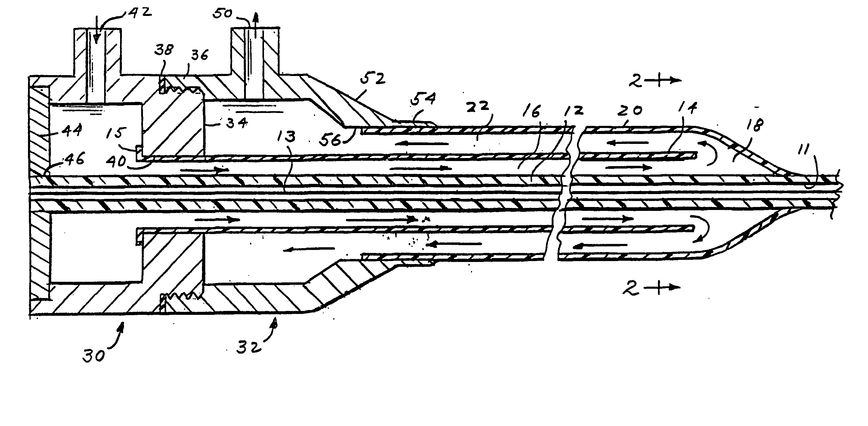
[0042] In each of the drawings, as described below, it should be understood that the wall thicknesses of the catheter and balloon lumens have been greatly exaggerated relative to other elements and to other dimensions for purposes of illustration.

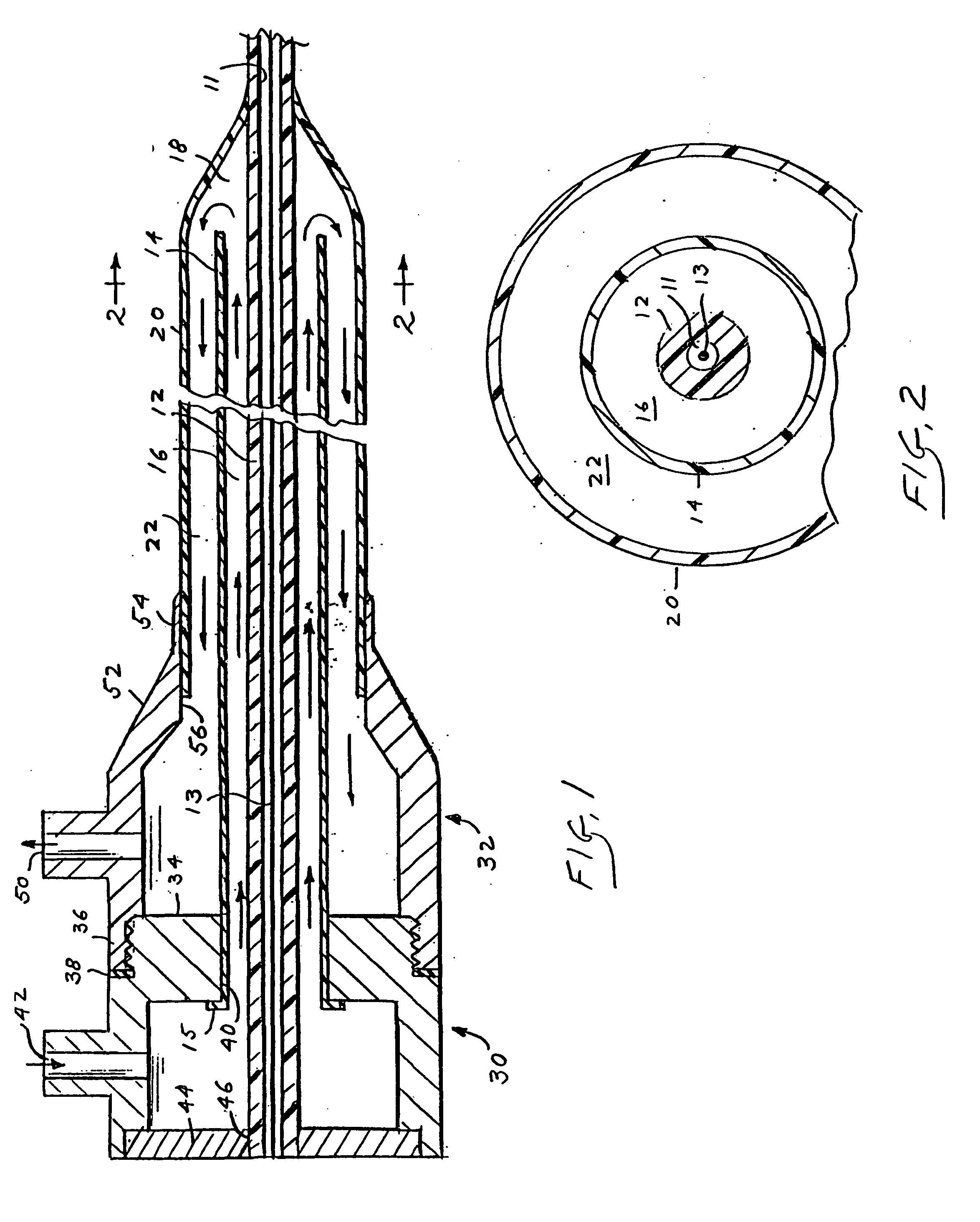
[0043]FIG. 1 shows a schematic longitudinal sectional view of a heat transfer catheter apparatus 10 according to the present invention comprising a substantially concentric, coaxial configuration of multiple lumens or channels. The concentric, coaxial arrangement of the multiple lumens can be better understood by reference to FIG. 2, a cross-sectional view taken along the line 2-2 of FIG. 1. Returning to FIG. 1, a first, inner catheter tube 12 defines a central conduit 11 receiving a guide wire 13. Catheter tube 12 may be of conventional, thick-walled construction or, alternatively, comprise very thin sidewalls. For purposes of this invention, the terms “very thin walls” or “very thin-walled” refer to elongated sleeves or catheters having ...


PUM


Abstract

Heat transfer catheter apparatus and methods of making and using same are disclosed wherein a fluid connection is provided between the distal portions of two adjacent, thin-walled, high strength fluid lumens to define a closed loop fluid circulation system capable of controlled delivery of thermal energy to or withdrawal of thermal energy from remote internal body locations.

Description

CROSS-REFERENCE TO RELATED APPLICATIONS [0001] This application is a continuation-in-part of both U.S. patent application Ser. No. 08 / 059,725, filed May 10, 1993, and now pending, which in turn was a continuation of U.S. patent application Ser. No. 07 / 522,178, filed May 11, 1990, now abandoned, and also of U.S. patent application Ser. No. 07 / 929,305, filed Aug. 13, 1992, and now pending. The disclosures of these related prior pending applications are incorporated herein by reference.BACKGROUND OF THE INVENTION [0002] The present invention relates generally to heat transfer catheter apparatus for internal body applications, and more particularly, to catheters adapted for delivering heat transfer fluids at temperatures above or below normal body temperatures to selected internal body sites that are relatively remote from the point of entry into the body for specialized medical applications. The heat transfer catheters of this invention may, in one embodiment, comprise fluid lumens tha...

Claims


Application Information

Patent Timeline
Patent Type & Authority Applications(United States)
IPC IPC(8): A61F2/958A61F7/00A61F7/12A61M25/00A61M29/02
CPCA61B2018/00166A61M2025/1086A61F2007/0054A61F2007/126A61M25/0009A61M25/0029A61M25/0032A61M25/1027A61M25/1029A61M25/104A61M29/02A61M2025/0025A61M2025/0031A61M2025/0034A61M2025/0036A61M2025/1031A61M2025/1072A61M2025/1075A61F7/123
Inventor SAAB
Owner ZOLL CIRCULATION
Why Eureka
Try Eureka