
Seismic data interpolation system

Inactive Publication Date: 2005-05-26
DIVESTCO
View PDF14 Cites 75 Cited by
  • Summary
  • Abstract
  • Description
  • Claims
  • Application Information

AI Technical Summary

Benefits of technology

[0022] In one embodiment, the step of obtaining polynomial fit parameters of the multi-order polynomial equation is solved numerically by a singular value decomposition of a matrix, C, defined by C=ULVT and in another embodiment a transformed coordinate system is utilized to speed up the computation time required to solve for the polynomial fit parameters of an interpolated trace.
[0024] In another embodiment, the specified location is a known location and the method is utilized as a means of reducing random noise associated with the trace data at that known location.

Problems solved by technology

In addition, azimuthal sampling is usually less than adequate (that is source to receiver azimuths tend to be similar rather than evenly distributed over 360 degrees) and the distribution of offsets (source to receiver distance) is unbalanced and inadequate.
However, as the cost of obtaining an ideally sampled dataset would be prohibitively expensive, the collection of seismic data must always be a balance between acceptable resolution and the cost of obtaining data with an acceptable resolution.
Moreover, the collection of seismic data is often affected by other limitations including the specific surface geography of an area where because of specific natural geographical features such as lakes or steep terrain, man-made features, such as roads or buildings, or environmental restrictions, such as wildlife sanctuaries, the placement of shots and geophones in particular areas is prevented, thus leading to incomplete images or images with decreased resolution in particular areas.
Still further, a common manifestation of inadequate sampling is a low signal-to-noise ratio in the final image.
Noise is a direct hindrance to the successful interpretation of seismic data, and great efforts are made to reduce noise.
If the spatial sampling is inadequate (ie geophones are too far apart), then spatial aliasing will result giving incorrect images.
In addition, various forms of unwanted coherent noise (as opposed to random noise) travel at velocities that differ from the primary (and desired) reflection energy.
A less than adequate dataset from the field can limit the quality of the image processing.
Shortcomings introduced by inadequate statistics in any of these steps can seriously impact the final image integrity.

Method used


Image

  • Seismic data interpolation system
  • Seismic data interpolation system
  • Seismic data interpolation system

Examples


examples

[0094] A number of tests were performed on both real and synthetic data.

[0095] Synthetic Data

[0096] Testing using synthetic data utilized a delta function approach. A zero phase wavelet is reflected from a tilted boundary with random source and receiver locations about a common mid-point (CMP). The gathered traces contain the same wavelet placed at calculated arrival times. With such an input data set, interpolation to the same locations has resulted in near perfect results.

[0097] Field Data

[0098] A few field-data sets have been utilized that provide satisfactory interpolation results as detailed below.

[0099] Sources form a grid with x and y intervals of dx=513 & dy=96 metres, with 6 shot lines oriented in the y direction, and 56 shots per line. Note that geographical features and dead shots either prevented a shot from being made or resulted in a no shot. The total number of live shots is 317 as shown in FIG. 3.

[0100] The shot data was received with receivers forming a grid w...


PUM


Abstract

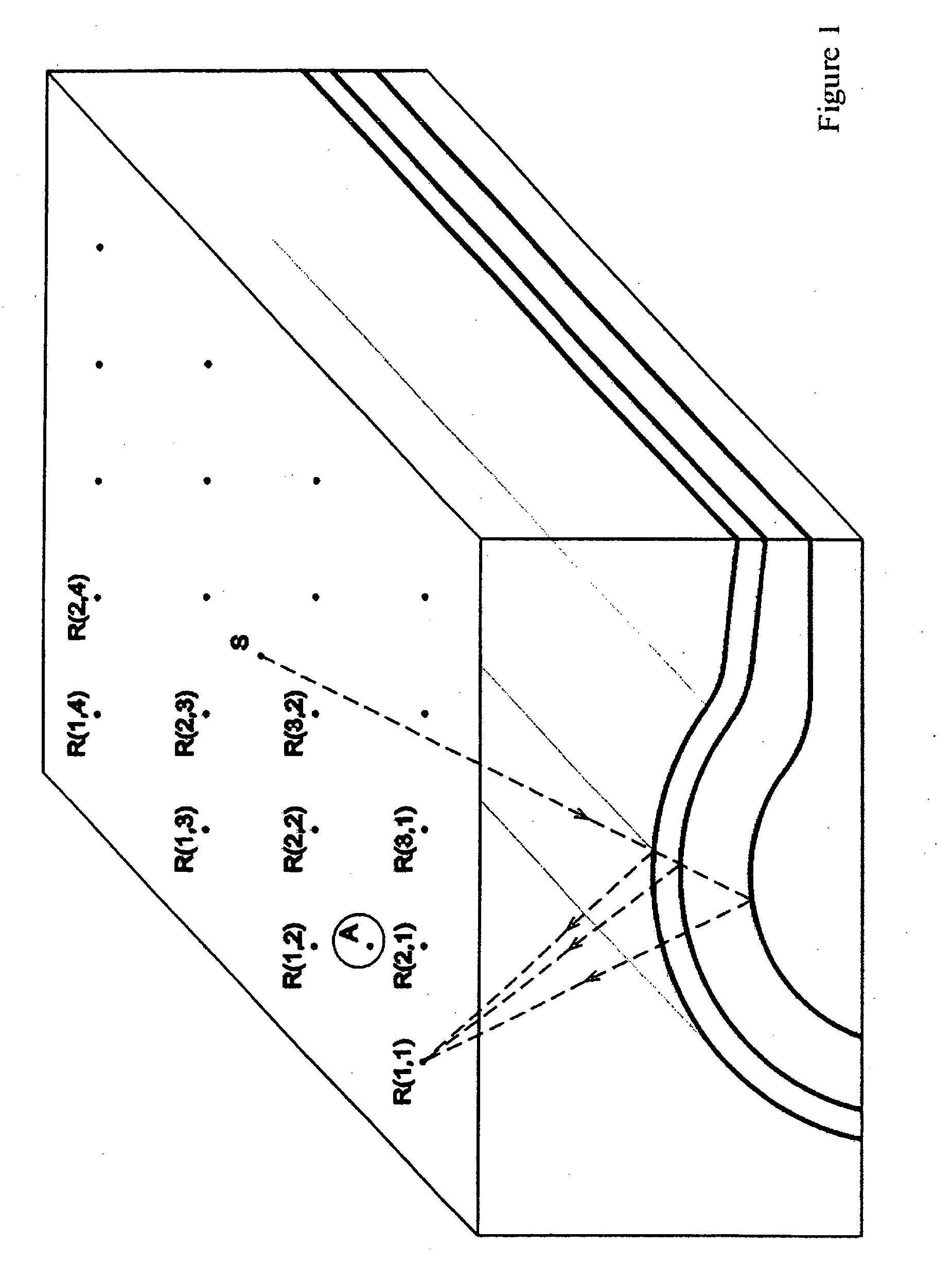
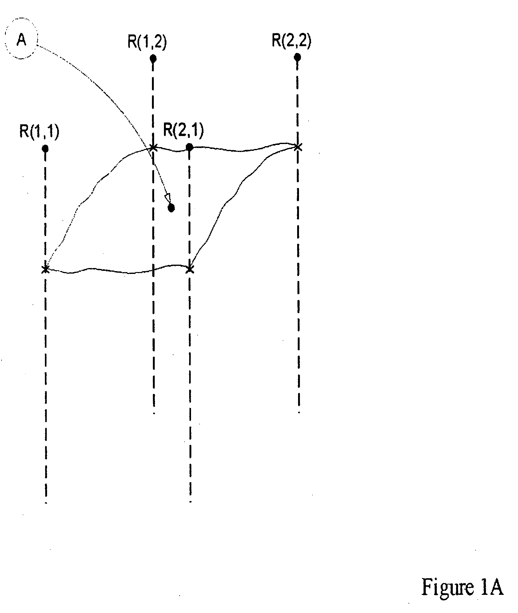
Seismic traces of 3D surveys are interpolated using polynomials in 4D space from a less densely sampled real data set of source points S(x,y) and receiver points R(x,y). Input seismic traces should be pre-processed by normal move out (NMO) and static corrections. Input traces contributing to each single interpolated trace are chosen from a selected number of traces closest to each interpolated trace in 4D space. The methodology in accordance with the invention is designed to minimize computational load. The amplitude of an interpolated trace is modeled with a two-term Amplitude vs. Offset (AVO) formulation.

Description

FIELD OF THE INVENTION [0001] Seismic traces of 3D surveys are interpolated using polynomials in 4D space from a less densely sampled real data set of source points S(x,y) and receiver points R(x,y). Input seismic traces should be pre-processed by normal move out (NMO) and static corrections. Input traces contributing to each single interpolated trace are chosen from a selected number of traces closest to each interpolated trace in 4D space. The methodology in accordance with the invention is designed to minimize computational load. The amplitude of an interpolated trace is modeled with a two-term Amplitude vs. Offset (AVO) formulation. BACKGROUND OF THE INVENTION [0002] In the oil exploration industry, seismic data is obtained to enable scientists and engineers to develop a picture of underlying rock formations. The reflection seismic method attempts to image the top few kilometres of the earth's crust by artificially creating a wavefield at the earth's surface and then recording t...

Claims


Application Information

Patent Timeline
IPC IPC(8): G01V1/28G06F19/00
CPCG01V2210/57G01V1/28
Inventor WANG, XISHUO
Owner DIVESTCO
Learn More