Retracting eye drape

US20050115569A1Inactive Publication Date: 2005-06-02DAVIS ANDREW PETER

Image

  • Retracting eye drape
  • Retracting eye drape
  • Retracting eye drape

Examples


Embodiment Construction

[0048] The present invention provides a new type of draping system, and method of applying the drape, prior to eye surgery. The drape is applied with the patient's eye closed, reducing the discomfort to the patient and risk of corneal surface abrasion. The drape and method of application also make it easier and less cumbersome for the surgeon to apply.

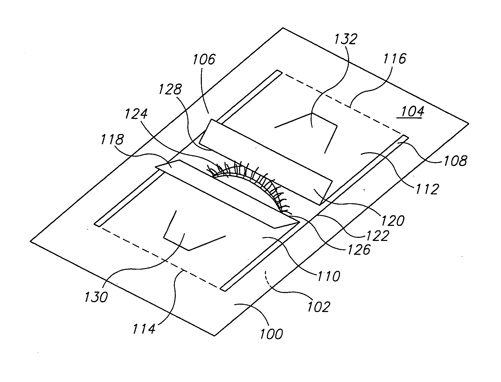
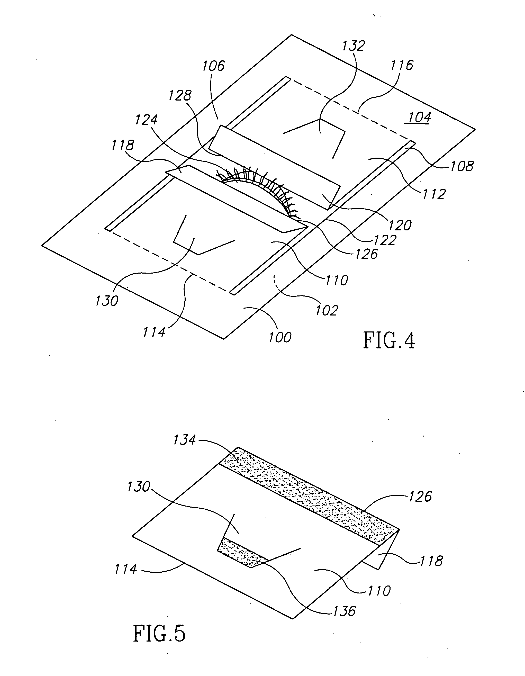
[0049] With reference to FIG. 4, a drape 100 is described having an adhesive surface 102, a non-adhesive surface 104, and a retraction area 106. Prior to application of the drape 100, the adhesive surface 102 is protected by a protective sheet (not shown) that can be pulled away to expose the adhesive surface 102. The retraction area 106 includes an open area 108 in the non-adhesive surface 104 and two retracting elements, an upper retraction member 110 and a lower retraction member 112, preferably attached to the non-adhesive surface 104 at upper member base 114 and lower member base 116, respectively.

[0050] Each retraction member 1...


PUM


Abstract

A retracting eye drape assembly is disclosed for use around a patient's eye to seclude and seal off the operative field during eye surgery. The drape assembly includes a retraction member connected to the drape and configured to engage the patient's eyelid, an extension member connected to the retraction member or to the drape and configured to substantially enclose the patient's eyelid, and a retraction flap configured to secure the patient's eyelid in a substantially retracted position. A method of applying an eye drape assembly is disclosed. After application of the drape to the patient's face, and while the patient's eyelid is closed, the patient's eyelid is engaged by a retraction member connected to the drape and retracted. While retracted, the patient's eyelid is substantially enclosed to seclude the eyelid and eyelashes from the operational area. The secluded eyelid and eyelashes are then secured in a retracted position.

Description

PRIORITY CLAIM [0001] This application claims priority to U.S. Provisional Application Nos. 60 / 526,443, filed Dec. 2, 2003, and 60 / 620,248, filed Oct. 19, 2004, which applications are hereby incorporated by reference in their entirety as if fully set forth herein.FIELD OF THE INVENTION [0002] This invention relates generally to surgical eye drapes and, more specifically, to a system and method for a retracting eye drape. BACKGROUND OF THE INVENTION [0003] As part of virtually every eye surgery, the facial area around the eye must be sealed off to expose the eye to the surgeon. Various techniques have been used to accomplish this goal. Most of the techniques incorporate the use of a sterilized surgical drape, typically made of plastic, having adhesive on one surface, together with an eyelid retraction device, typically a speculum. [0004] The typical prior art technique for draping an eye 10 having an upper eyelid 12 with upper eyelashes 14 and a lower eyelid 16 having lower eyelashes...

Claims


Application Information

Patent Timeline
02 Jun 2005
Publication
US20050115569A1
IPC
A61B17/02; A61B19/08; A61B46/23
CPC
A61B17/0231; A61B2019/085; A61B19/08; A61B46/00; A61B2046/205
Inventors
DAVIS, ANDREW PETER