Rubber crawler and crawler traveling equipment

Active Publication Date: 2005-06-02
FUKUYAMA GOMU KOGYO
View PDF12 Cites 15 Cited by
  • Summary
  • Abstract
  • Description
  • Claims
  • Application Information

AI Technical Summary

Benefits of technology

[0039] It is preferable that the inside circumference of the rubber crawler has the central part of the cross direction made high and the edges thereof made low. According to this, mud drainage is well, thereby preventing mud from gathering between the crawler and the tires, preventing the crawler from g

Problems solved by technology

The following construction is made to solve inconveniences due to no devices for adjusting crawler extension in a traveling equipment according to a tire specification, which are new problems caused by suspendedly

Method used


Image

  • Rubber crawler and crawler traveling equipment
  • Rubber crawler and crawler traveling equipment
  • Rubber crawler and crawler traveling equipment

Examples


Embodiment Construction

[0061] Embodiments of the present invention are explained according to drawings as follows.

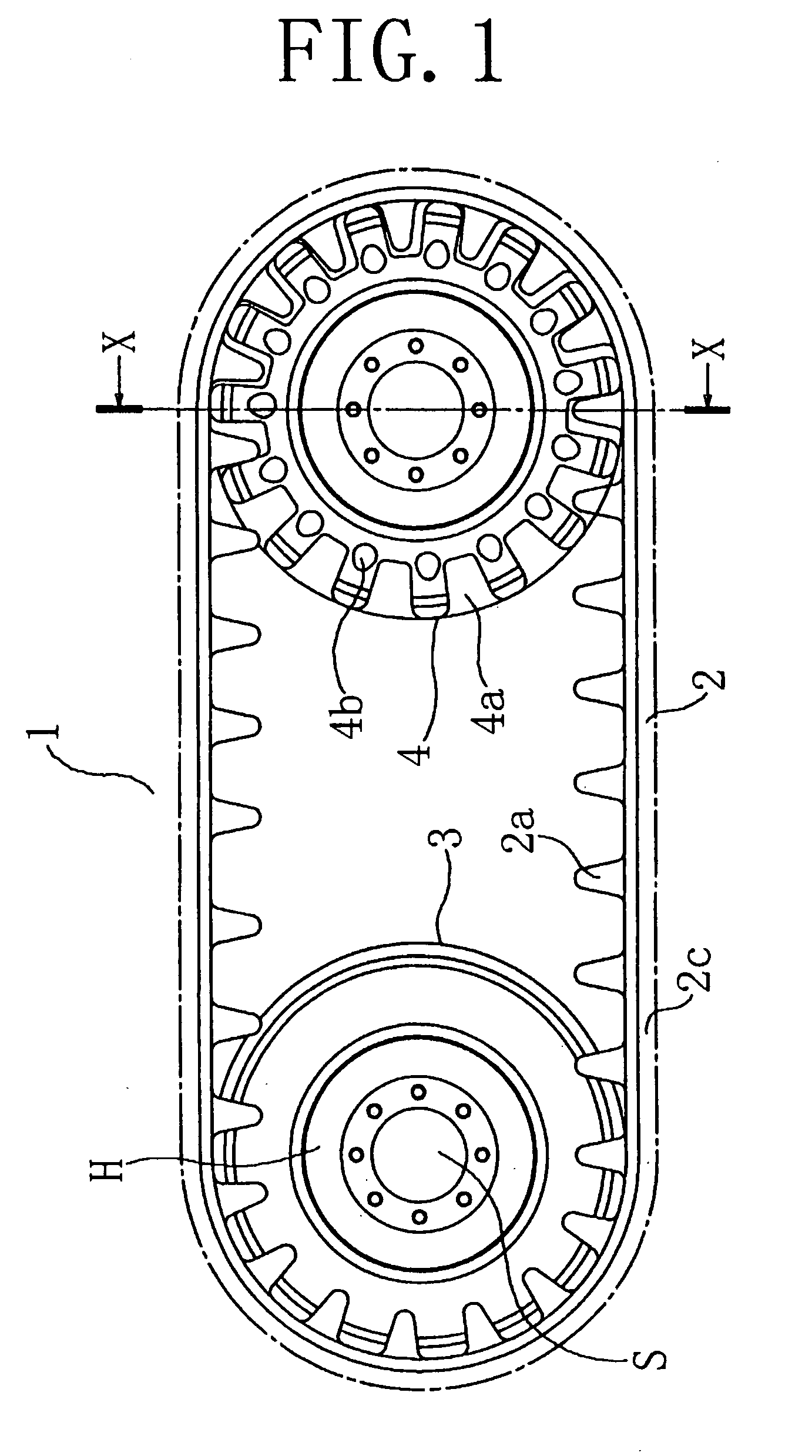
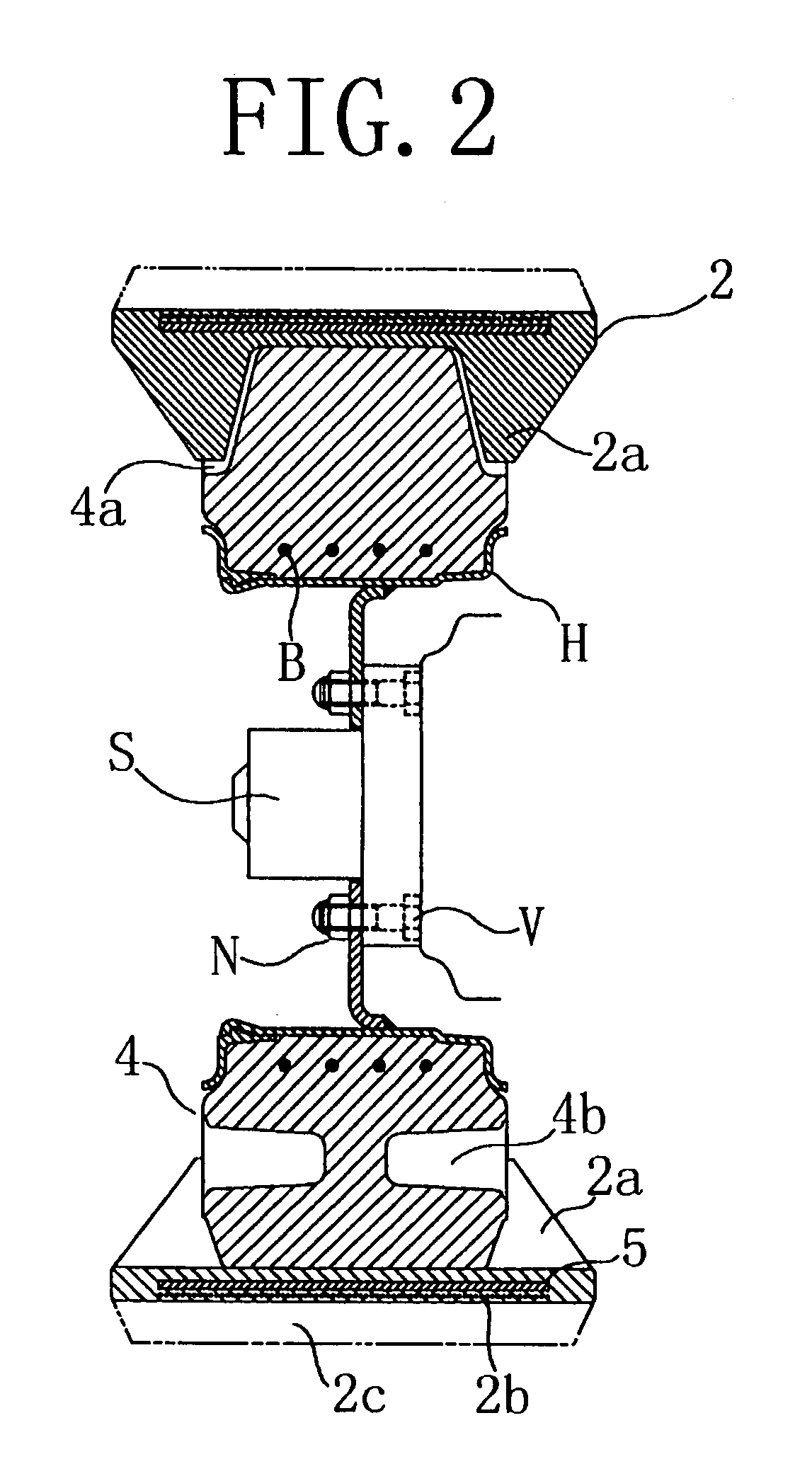
[0062]FIG. 1 is a side view of a rubber crawler traveling equipment related to the present invention, and FIG. 2 is a section view taken on line X-X of FIG. 1.

[0063]FIGS. 1, 2 show a traveling equipment 1 in the first embodiment of the present invention, which is a skid steering traveling equipment 1 having a rubber crawler 2 installed on tires 3, 4. In this embodiment, the rubber crawler 2 is suspendedly installed between a coupled driving wheel 3 comprising a hollow tire for enlarging and reducing the outside diameter dimension and a driving wheel 4 comprising a perforated solid tire.

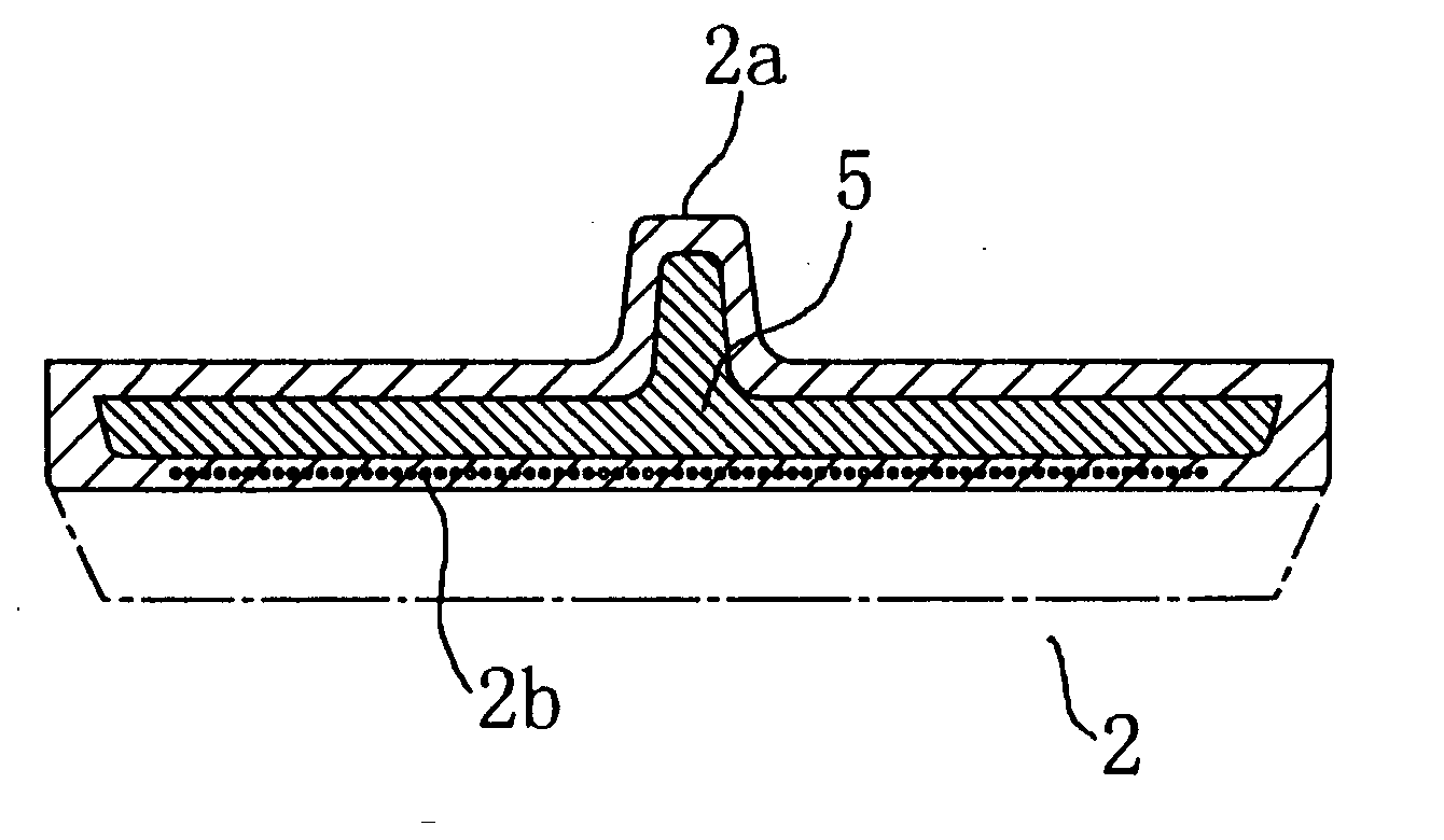
[0064] The perforated solid tire is provided with an engaging hole 4a for transmitting driving force from the traveling equipment due to engaging with guide protrusions 2a of the rubber crawler 2. Side holes 4b are formed to each side surface of the driving tire 4 to keep cushion property.

[0065] The travelin...


PUM


Abstract

Rubber crawler traveling equipment (1) capable of reducing the weight and cost of a rubber crawler, and commonizing a light-speed traveling to a traveling according to a tire specification and a traveling to a traveling according to a crawler specification, wherein core members (5) formed of plastic material are embedded in a rubber crawler (2) instead of metallic core members embedded in a conventional rubber crawler and the rubber crawler (2) is suspendedly installed on tires (3, 4), whereby the rubber crawler (2) can be easily attached and detached and the extension thereof can also be adjusted by regulating the internal pressure of the hollow tire (3).

Description

TECHNICAL FIELD [0001] The present invention relates to a rubber crawler and a crawler traveling equipment, which are installed on tires of industrial vehicles represented by construction machines, civil work machines, agricultural cars, carrier, snow removing cars and cargo vehicles such as a fork lift truck. PRIOR ART [0002] Skid steering industrial vehicles according to a tire specification are described in Japanese Patent publication No. 30588 of 1985 (FIG. 19A), Japanese Patent Publication No. 5400 of 1996, Japanese Utility Model Laid-open Publication No. 91387 of 1980 (FIG. 19C), Japanese Utility Model Laid-open Publication No. 125066 of 1990 and Japanese Utility Model Publication No. 24439 of 1995 (FIG. 19B). There are, for example, skid steering loaders shown in FIG. 19A and FIG. 19B and a multiwheeled traveling car shown in FIG. 19C. In these figures, 13 is a tire. [0003] Besides, a crawler traveling equipment for an agricultural car such as a combine or a harvester is disc...

Claims


Application Information

Patent Timeline
IPC IPC(8): B62D55/253
CPCB62D55/244B62D55/253
Inventor KATOH, YUSAKUNORITOH, TATSUYAKIMURA, HIDEKI
Owner FUKUYAMA GOMU KOGYO
Why Eureka
Try Eureka