Stator for vehicular rotary electric machine and a manufacturing method thereof
a technology of rotary electric machines and stators, which is applied in the manufacture of stator/rotor bodies, dynamo-electric components, windings, etc., can solve the problems of inability to meet the needs of adjacent electrical conductors, and achieve the effect of improving cooling efficiency
- Summary
- Abstract
- Description
- Claims
- Application Information
AI Technical Summary
Benefits of technology
Problems solved by technology
Method used
Image
Examples
first embodiment
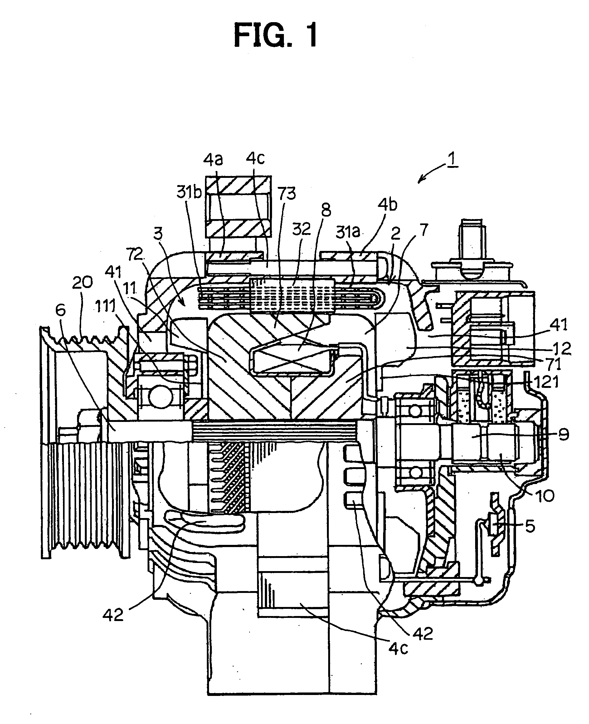
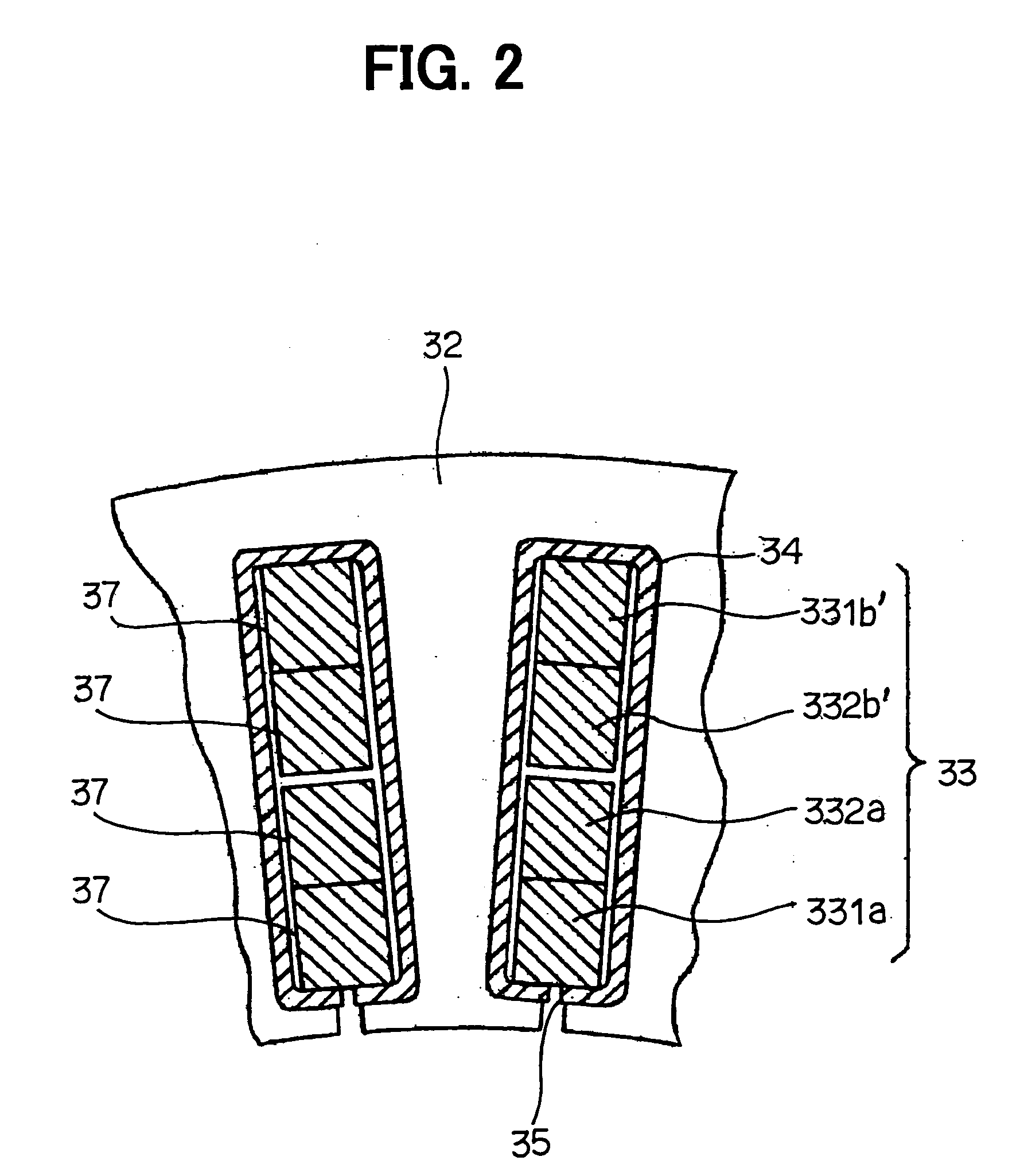
[0075]FIGS. 1 through 7 illustrate a first embodiment of the present invention, FIG. 1 is a cross-sectional view of major parts of a vehicular AC generator and FIGS. 2 through 7 are explanatory diagrams of the stator in this embodiment.
[0076] Vehicular AC generator 1 includes a stator 2 that functions as an armature, a rotor 3 as a field coil, a front housing 4a and a rear housing 4b supporting the rotor 3 and fixing the stator 2 from both sides with fastening bolts 4c, and rectifiers 5 for converting AC power into DC power. The rotor 3 rotates integrally with a shaft 6 and includes Lundell-type pole cores 7, field coils 8, slip rings 9 and 10, and an air blowing system including a diagonal current fan 11 and a centrifugal fan 12. The shaft 6 is joined to a pulley 20 and is rotated by an engine (not shown) mounted on the vehicle.
[0077] A typical Lundell-type pole core 7 has a pair of pole cores. The Lundell-type pole core 7 includes a boss 71 assembled to the shaft 6, disks 72 ext...
second embodiment
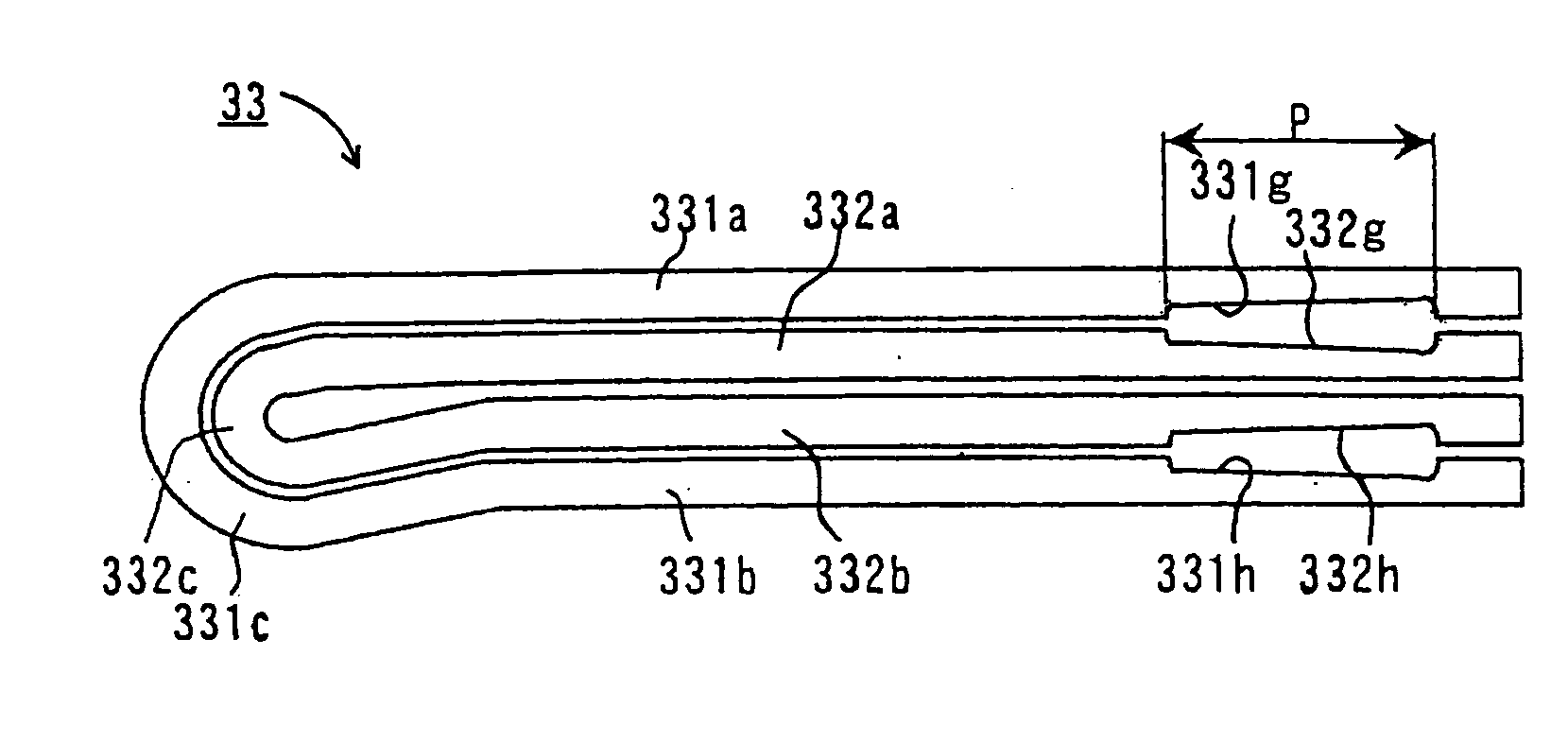
[0113] In a second embodiment of the present invention, even when the adjoining conductor segments at the coil end cross each other in a twisted state, clearances are secured in the intersecting portions of adjacent conductor segments by forming radial indentations.
[0114] The manufacturing process of the stator 2 of the second embodiment includes: a step of forming indentations in the side faces of each of the conductor segments 331 and 332 by pressing, the indentations being slanted so as to be oriented in the radial direction when the segments are twisted; a step of inserting the conductor segments 331 and 332 in the slots 35 so that they adjoin each other in the radial direction; a step of bending each of the conductor segments and radially adjacent segments (for example, 331a and 332a, and 332b′ and 331b′) in different circumferential directions at a predetermined pole pitch angle in a twisting fashion such that the indentations formed in the side faces of the adjacent conducto...
third embodiment
[0126] The distinguishing feature of the third embodiment is that protrusions are formed at the ends (including the bond areas) of the conductor segments at the coil end. The protrusions are offset toward the other conductor segments to be bonded.
[0127]FIG. 26 illustrates the large and small segments 331 and 332 in the third embodiment. The large and small segments 331 and 332 are respectively formed with protrusions 331k, 3311, 332k, and 3321 on the faces of the straight portions 331a, 331b, 332a, and 332b which face each other when the turn portions 331c and 332c are aligned in multiple layers. FIG. 27 is an enlarged view near the end of the large segment 331 formed with the protrusion 3311. The end of the large segment 331 is protruded, by pressing or the like, toward the side of the other conductor segment, to the bond area of which the bond area 331j of the large segment 331 will be bonded. The offset amount h1 of the protrusion 3311 toward that direction on the side of the bo...
PUM
| Property | Measurement | Unit |
|---|---|---|
| depth | aaaaa | aaaaa |
| area | aaaaa | aaaaa |
| depths | aaaaa | aaaaa |
Abstract
Description
Claims
Application Information
 - R&D
- Intellectual Property
- Life Sciences
- Materials
- Tech Scout
- Unparalleled Data Quality
- Higher Quality Content
- 60% Fewer Hallucinations
Browse by: Latest US Patents, China's latest patents, Technical Efficacy Thesaurus, Application Domain, Technology Topic, Popular Technical Reports.
© 2025 PatSnap. All rights reserved.Legal|Privacy policy|Modern Slavery Act Transparency Statement|Sitemap|About US| Contact US: help@patsnap.com


