Control constant adjusting apparatus

a constant adjustment and control technology, applied in the direction of electric controllers, program control, instruments, etc., can solve the problems of difficult to reflect the compensation amount of the load disturbance in the model, delay in the model speed control system, and time-consuming, and achieve the effect of high identification accuracy and time taken

Inactive Publication Date: 2005-06-02
YASKAWA DENKI KK
View PDF7 Cites 13 Cited by
  • Summary
  • Abstract
  • Description
  • Claims
  • Application Information

AI Technical Summary

Benefits of technology

[0011] By inputting a feedforward signal from the speed control member to the estimation member, a model speed tends to match with an actual speed and also when there is load disturbance, its influence

Problems solved by technology

Also, in the conventional control constant adjusting apparatus described above, the motor speed is set as a speed command of a model speed control part, so that there is a problem that delay in a model speed control system occurs and it takes time to reach identification since a model motor speed is difficult to match with the motor speed.
Further, when there is load disturbance such as mechanical vibration or friction, the amount of compensation of the load disturbance is

Method used


Image

  • Control constant adjusting apparatus
  • Control constant adjusting apparatus
  • Control constant adjusting apparatus

Examples


Embodiment Construction

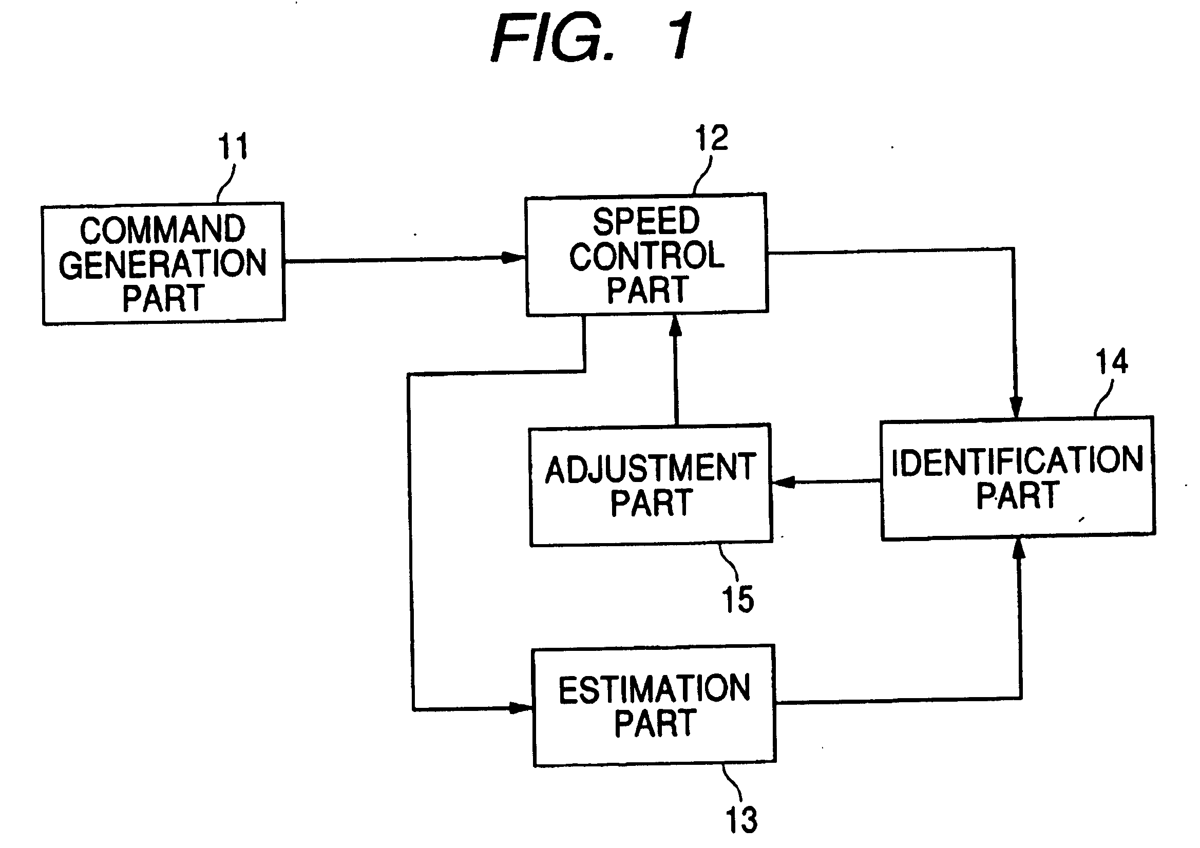
[0022] Referring to FIG. 1, a control constant adjusting apparatus of a first embodiment of the invention includes a command generation part 11, a speed control part 12, an estimation part 13, an identification part 14 and an adjustment part 15.

[0023] The command generation part 11 outputs a speed command Vref to the speed control part 12.

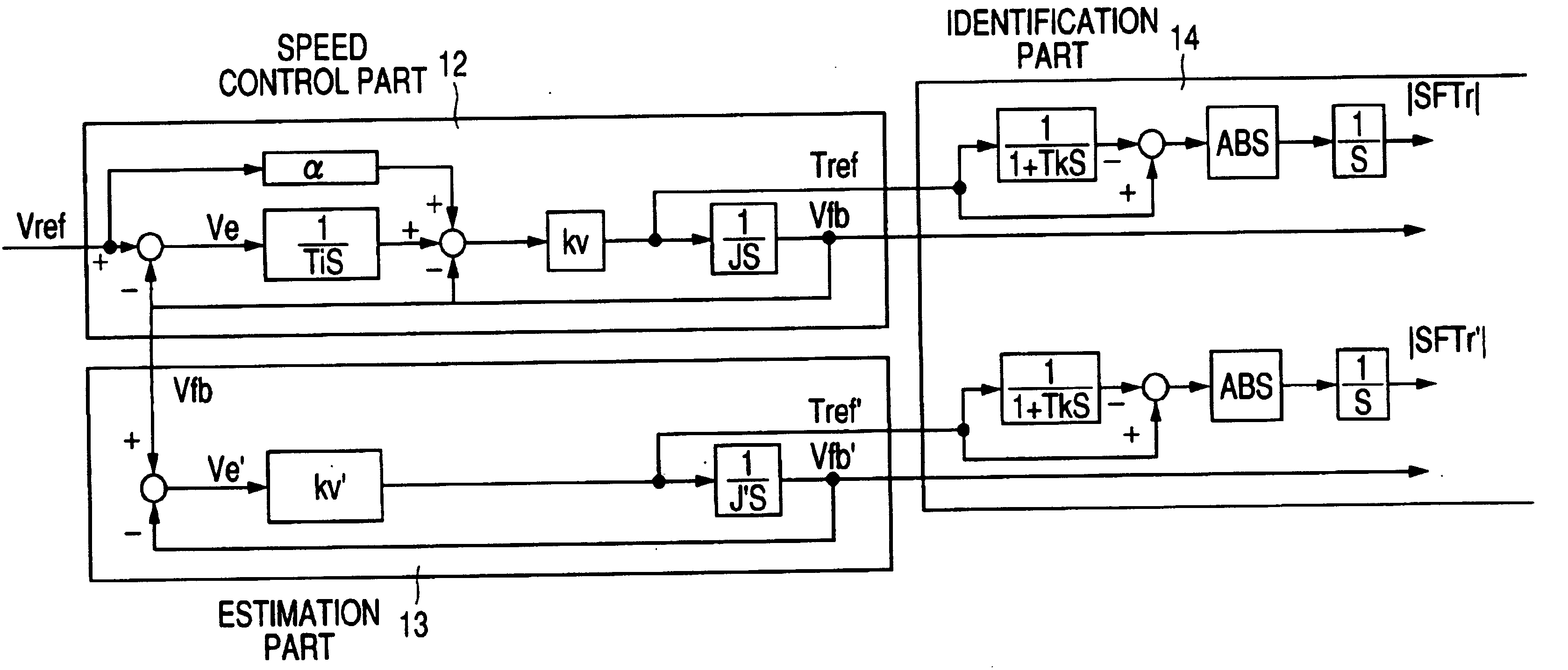
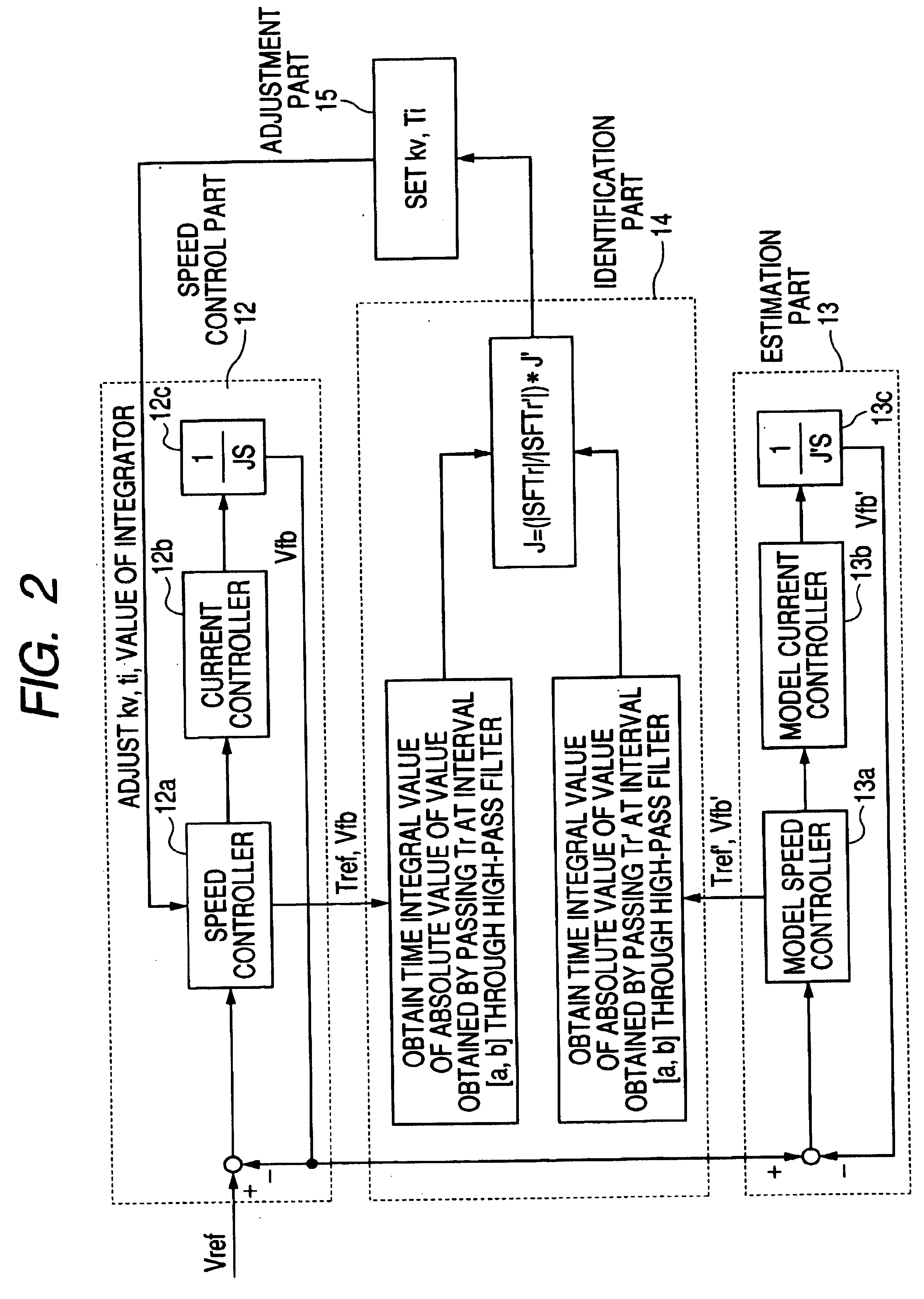
[0024] The speed control part 12 performs speed control so that a motor speed Vfb matches with the inputted speed command Vref, and outputs a torque command Tref and the motor speed Vfb to the identification part 14, and also outputs the motor speed Vfb to the estimation part 13.

[0025] The estimation part 13 performs speed control so that a model speed Vfb′ estimated by using a motor model in this estimation part 13 matches with the motor speed Vfb inputted as a target command, and outputs a model torque command Tref′ and the model speed Vfb′ to the identification part 14.

[0026] The identification part 14 obtains an inertia ratio J / J′ between a...


PUM


Abstract

A control constant adjusting apparatus in a control apparatus of a robot or a machine tool, etc. is disclosed. This control constant adjusting apparatus includes a speed control part (12), an estimation part (13), an identification part (14) and an adjustment part (15) . The identification part (14) makes identification of inertia J obtained from a ratio between a value |SFTr| in which an absolute value |FTr| of a value FTr obtained by passing a torque command Tref of the speed control part (12) through a predetermined high-pass filter is integrated with respect to time at a predetermined interval [a, b] and a value |SFTr′| in which an absolute value |Ftr′| of a value FTr′ obtained by passing a model torque command Tref′ of the estimation part (13) through a predetermined high-pass filter is integrated with respect to time at the same interval only when a speed Vfb′ of a model in the estimation part (13) matches with a motor speed Vfb in the speed control part (12) at a value other than zero.

Description

TECHNICAL FIELD [0001] The present invention relates to a control constant adjusting apparatus having a function of identifying an inertial and adjusting a gain of a control system required along with the identification particularly in the case that variation occurs in inertia of a load during the operation in a control apparatus of a robot or a machine tool, etc. BACKGROUND ART [0002] Conventionally, in the case that variation occurs in inertia of a load which is a controlled object during operation of a motor, as an apparatus for identifying its inertia, for example, there is a control constant adjusting apparatus in Japanese Patent No. 3,185,857 proposed by the present applicant. [0003] This apparatus includes a speed control part for determining a torque command so that an actual motor speed matches with a speed command inputted and controlling the motor speed, an estimation part for simulating the speed control part so that a speed of a model matches with the motor speed and an...

Claims


Application Information

Patent Timeline
IPC IPC(8): H02P5/00H02P23/00
CPCH02P23/005H02P5/00H02P23/18G05B13/02G05B19/0405
Inventor TSURUTA, KAZUHIROUMEDA, NOBUHIROINOKI, KEISEI
Owner YASKAWA DENKI KK
Why Eureka
Try Eureka