Bearing for heat dissipating fan

a technology for heat dissipation fans and bearings, which is applied in the direction of bearing cooling, sliding contact bearings, mechanical equipment, etc., can solve the problems of increased noise of fans, unoptimized lubricating system in the above structure, etc., and achieve the effect of reducing consumption and effectively preventing lubricant leakag

Inactive Publication Date: 2005-06-02
SONICEDGE INDS CORP
View PDF3 Cites 31 Cited by
  • Summary
  • Abstract
  • Description
  • Claims
  • Application Information

AI Technical Summary

Benefits of technology

[0008] The present invention provides an improved bearing for a heat dissipation fan, which uses blockage of a central column and a through hole of a

Problems solved by technology

However, the lubricating system in the above structure is not optimized for having the following drawbacks: 1.
Consequently, noise

Method used


Image

  • Bearing for heat dissipating fan
  • Bearing for heat dissipating fan
  • Bearing for heat dissipating fan

Examples


Embodiment Construction

[0019] Reference will now be made in detail to the preferred embodiments of the present invention, examples of which are illustrated in the accompanying drawings. Wherever possible, the same reference numbers are used in the drawings and the description to refer to the same or like parts.

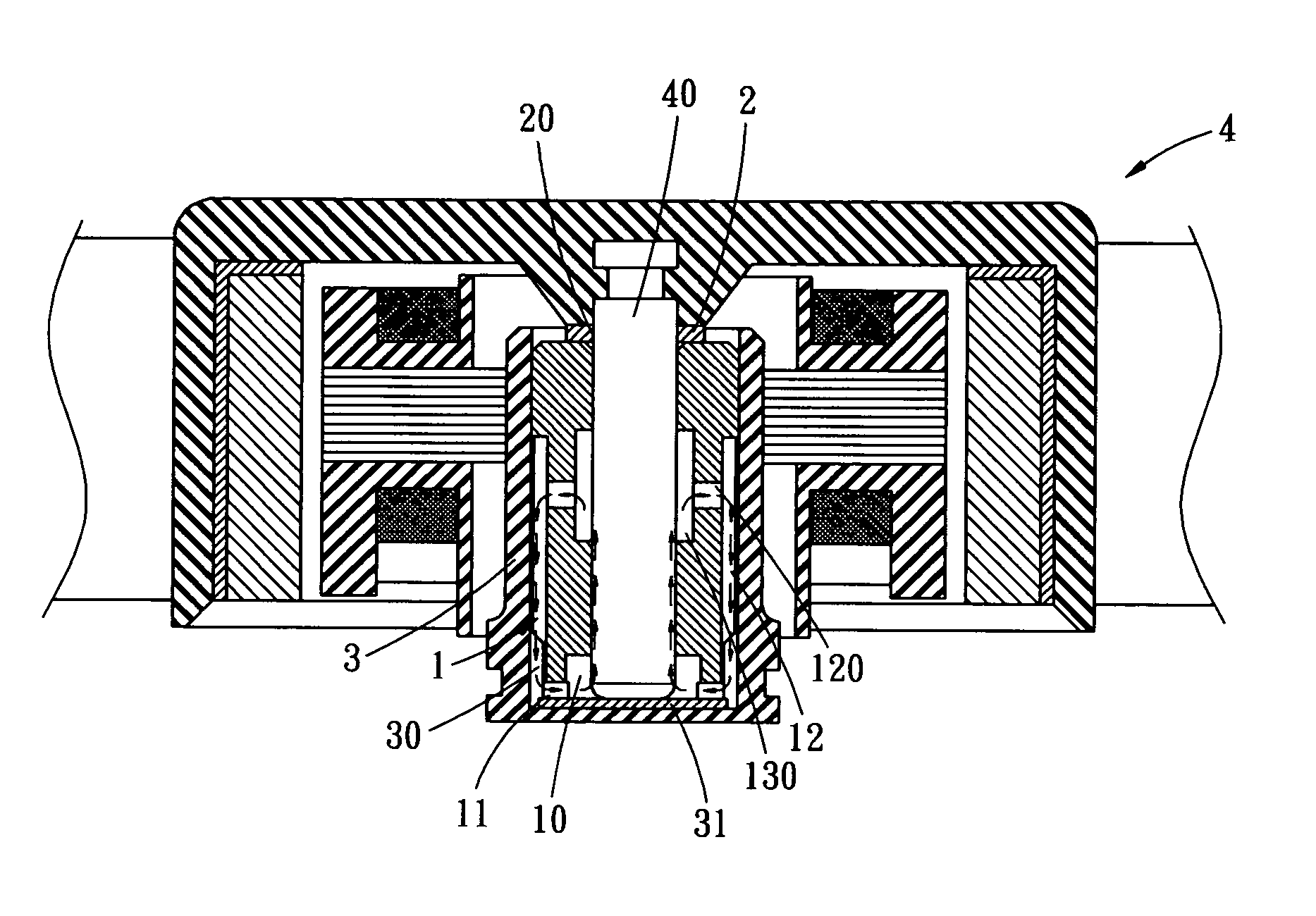
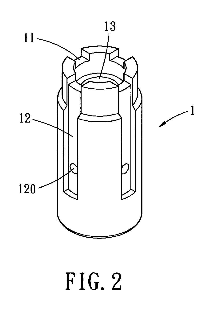
[0020] Referring to FIGS. 2-3, the present invention provides a hydraulic bearing 1 including an oil chamber 10 for containing liquid lubricant therein. Preferably, the oil chamber 10 includes a cylindrical sidewall with one end open and the other end closed. The edge of the sidewall of the oil chamber 10 at the open end is partially recessed to form notches 11 as shown in FIG. 2, and the external surface of the sidewall is partially recessed to form oil slots 12 aligned with the notches 11. In the embodiment as shown in FIG. 2, the oil slots 12 are not formed through the elongate length of the sidewall. That is, the oil slots 12 extend from the open end, but do not reach the closed end of the oil ...


PUM


Abstract

An improved bearing for a heat dissipation fan has an oil chamber for containing lubricant. The oil chamber has a sidewall extending between one open end and one closed end. The closed end is perforated with a through hole, and an edge of the sidewall at the open end is partially recessed to form at least one notch. An external surface of the sidewall is partially recessed along an elongate direction to form at least one oil slot aligned with the notch, the recessed external sidewall is further perforated with a through hole. An O-ring is disposed adjacent to the closed end of the oil chamber. The O-ring has an aperture aligned with the through hole of the closed end. An axial column is inserted into the oil chamber through the aperture of the O-ring and the through hole of the closed end. An external sleeve is used for receiving the oil chamber therein. The central axis column is operative to rotate within the oil chamber, such that the lubricant contained in the oil chamber is driven to flow upwardly through the notch into the oil slot. The axial column is so configured to prevent the lubricant from flowing external to the oil chamber via the through hole of the closed end.

Description

BACKGROUND OF THE INVENTION [0001] The present invention relates to an improved bearing for a heat dissipation fan, and more particular, to an improved bearing which uses an external lid and a through hole of an oil tank to effective prevent the liquid lubricant to leak out of the fan. Further, the liquid lubricant is guided to reflow into the hydraulic bearing to suppress consumption of the liquid lubricant, so as to prolong the lifetime of the central axis and hydraulic bearing and reduce noise caused by friction. [0002] The commonly seen heat dissipation fan structures are normally installed in electronic or electric device to dissipate heat generated by operation of the electronic or electric device. The electronic or electric device is protected from high temperature to obtain a longer lifetime. The electronic or electric device includes computer motherboard, VCR or copy machine. [0003]FIG. 1 shows a conventional heat dissipation fan structure 1a. As shown, the fan structure1a ...

Claims


Application Information

Patent Timeline
IPC IPC(8): F16C17/10F16C33/10F16C37/00H02K7/08
CPCF16C17/10H02K7/085F16C37/002F16C33/1085
Inventor CHEN, ABINCHEN, SHIH H.
Owner SONICEDGE INDS CORP
Why Eureka
Try Eureka