Optical switch and a control method thereof

a control method and optical switch technology, applied in the field of optical switch, can solve the problems of optical coupling failure, large loss, and light beam failure to couple optically

Inactive Publication Date: 2005-06-02
HITACHI LTD
View PDF9 Cites 7 Cited by
  • Summary
  • Abstract
  • Description
  • Claims
  • Application Information

AI Technical Summary

Benefits of technology

[0007] Accordingly, an object of the present invention is to provide a compact optical switch which can solve the aforementioned problems encountered in the conventional example and can permit moving mirrors to keep optimum attitudes in correspondence with a change in temperatures in the installation environment of the optical switch.

Problems solved by technology

In the event that a light beam deviates from the end face of an output-side collimator lens, optical coupling fails.
Even when entering the end face of the output-side collimator lens, the light beam will fail to couple optically or a large loss will be incurred if its incident angle is outside a proper range.
However, as the temperature in the optical switch installation environment changes, the relative position between a collimator lens array and a mirror lens array changes and the optical coupling possibly fails even if predetermined attitudes of the moving mirrors are maintained.
Otherwise, a large loss will possibly be incurred.
Or, when the temperature in the optical switch system per se rises owing to continuous switching, the output of an electrical circuit changes and the moving mirrors will possibly fail to keep their predetermined attitudes.
In the method disclosed in the JP-A-2001-117025, the optical translation units before and after the optical switch are indispensable and disadvantageously, they make the construction complicated.
In addition, since two optical translation units are installed in respect of individual N ports, totaling 2N, and as a result, the size of equipment increases.

Method used


Image

  • Optical switch and a control method thereof
  • Optical switch and a control method thereof
  • Optical switch and a control method thereof

Examples


Embodiment Construction

[0027] Embodiments of the invention will be described hereunder in greater detail by making reference to the drawings. The present invention is in no way limited to configurations described in the specification and is not prevented from being applied with present-day known techniques or newly developable known techniques.

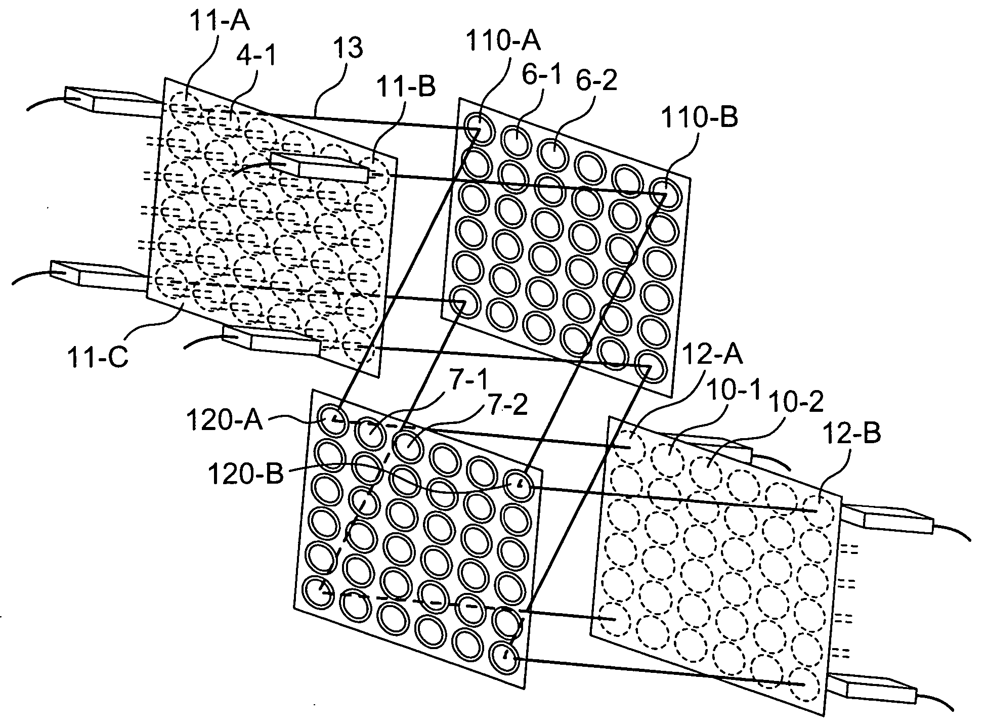
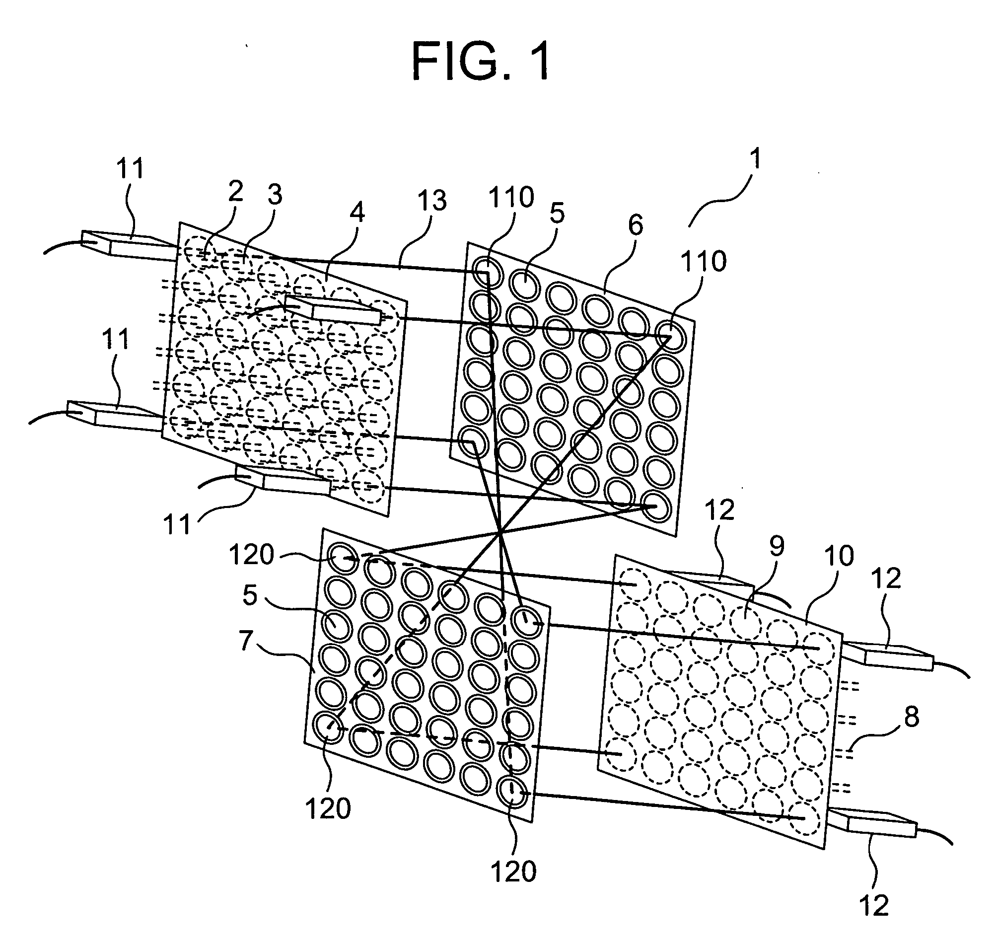
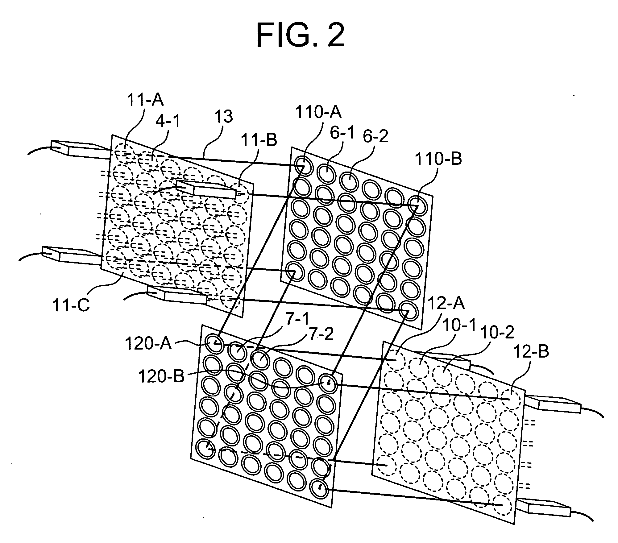
[0028]FIG. 1 is a schematic perspective view of an optical switch according to a first embodiment of the invention. The optical switch 1 comprises, as constituent components, an input-side collimator lens array 4 having arrayed input-side collimator lenses 3 optically coupled to a plurality of input-side optical fibers 2, primary and secondary mirror arrays 6 and 7 each having two-axially swingably movable, arrayed moving mirrors 5 and an output-side collimator lens array 10 having arrayed output-side collimator lenses 9 optically coupled to output-side optical fibers 8. The moving mirrors 5 of each of the primary mirror array 6 and the secondary mirror array 7 are...


PUM

PropertyMeasurementUnit
diameteraaaaaaaaaa
anglesaaaaaaaaaa
control anglesaaaaaaaaaa

Abstract

An optical switch for switching communication light beams propagating through a plurality of optical fibers. The switch includes a plurality of input-side lenses, a plurality of moving mirrors, a plurality of output-side lenses, light emitting units, and light receiving units arranged for optical communication. The plurality of input-side lenses include first input-side lenses to which communication light beams coming from first external units and propagating through input-side optical fibers connect optically and second input-side lenses to which the light beams from the light emitting units connect optically. The plurality of output-side lenses include first output-side lenses for causing light beams passing therethrough to optically connect to second output-side optical fibers adapted to propagate the communication light beams to second external units and second output-side lenses for causing the light beams coming from the light emitting units and passing therethrough to optically connect to the light receiving units.

Description

BACKGROUND OF THE INVENTION [0001] The present invention relates to an optical communication system using optical fibers and more particularly to an optical switch using a technique of microelectro mechanical systems (MEMS). [0002] In an optical communication system, N×N optical switches are required at a relay point of communication network, which switches can connect arbitrary one of communication light beams transmitted to N input ports through optical fibers to arbitrary one of N output ports and can switch these connections freely. In the past, to meet this requirement, light beams have once been converted into electrical signals and after being subjected to switching, the electrical signals have been converted into light beams. In recent years, an optical switch has been developed which can perform switching of light beams while keeping them intact. [0003] Available as a technique of optically monitoring optical connections in an optical switch is JP-A-2001-117025 based on U.S...

Claims


Application Information

Patent Timeline
Patent Type & Authority Applications(United States)
IPC IPC(8): G02B6/26G02B26/08G02B6/35G02B6/42
CPCG02B6/3512G02B6/3556G02B6/3582G02B6/359G02B6/4204G02B26/08
Inventor OKADA, RYOJIISHIKAWA, TADAAKI
Owner HITACHI LTD
Why Eureka
Try Eureka