Plastic optical fiber, plastic optical fiber preform and method for manufacturing preform

a technology of plastic optical fiber and preform, which is applied in the field of optical fiber, can solve the problems of high cost of manufacturing fragile multi-mode glass optical fiber, and difficult and expensive alignment and connection of glass optical fiber

Inactive Publication Date: 2005-06-02
SAMSUNG ELECTRONICS CO LTD
View PDF2 Cites 1 Cited by
  • Summary
  • Abstract
  • Description
  • Claims
  • Application Information

AI Technical Summary

Benefits of technology

[0014] Accordingly, the present invention has been made to solve the above-mentioned problems occurring in the prior art and provides additional advantages, by providing a plastic optical fiber capable of adjusting the distributions of effective refractive indices, a plastic optical fiber perform, and a method for manufacturing the preform.

Problems solved by technology

Due to its size, it is very difficult and expensive to align and connect a glass optical fiber.
However, the cost of manufacturing the multi-mode glass optical fiber is high and the multi-mode glass optical fiber is fragile.
As such, the multi-mode glass optical fiber is not widely used.
Instead, metal lines such as twisted pairs or coaxial cables are frequently used in short distance communication having a range within 200 m. However, since the metal lines have a maximum information transmission speed or a transmission bandwidth of 150 Mbps, it cannot meet the recent asynchronous transfer mode (ATM) standard, which requires a transmission speed of 625 Mbps.
Since the plastic optical fiber having the SI structure has a large modal dispersion, a signal cannot have a transmission speed faster than that of the metal lines.
However, during the polymerization process, it is not easy to selectively adjust the distributions of refractive indices for a desired distribution and to achieve distributions of refractive indices that continuously increase or decrease.
Further, it is difficult to cause diffusion for changing refractive indices gradually in a short time during the actual extrusion.
Therefore, it is difficult to manufacture an optical fiber which has distributions of refractive indices continuously increasing or decreasing from the clad to the core.

Method used


Image

  • Plastic optical fiber, plastic optical fiber preform and method for manufacturing preform
  • Plastic optical fiber, plastic optical fiber preform and method for manufacturing preform
  • Plastic optical fiber, plastic optical fiber preform and method for manufacturing preform

Examples


Embodiment Construction

[0029] Hereinafter, a preferred embodiment according to the present invention will be described with reference to the accompanying drawings. The same reference numerals are used to designate the same elements as those shown in other drawings. For the purposes of clarity and simplicity, a detailed description of known functions and configuration incorporated herein will be omitted as it may make the subject matter of the present invention unclear.

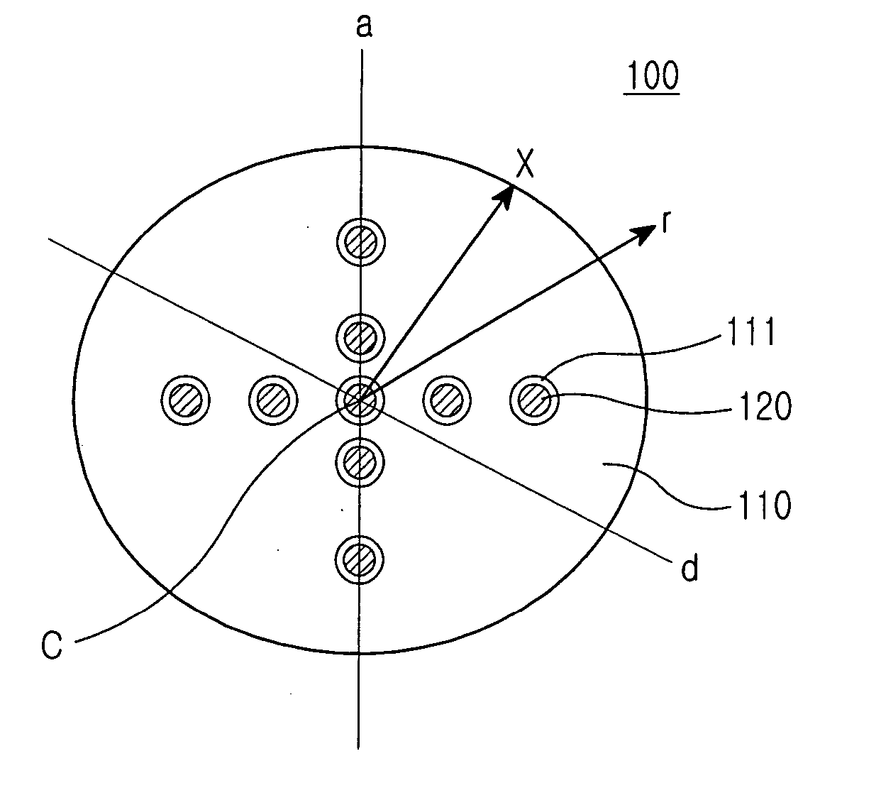
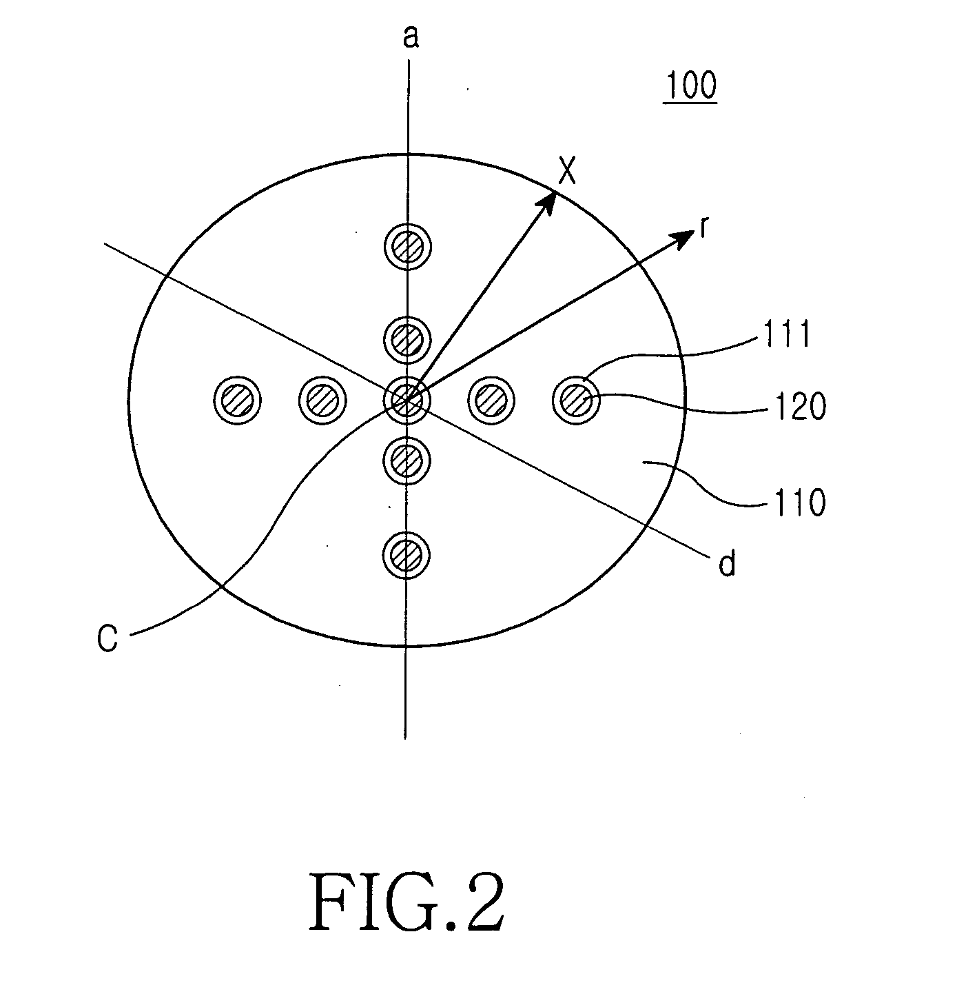
[0030]FIG. 2 is a cross-sectional view illustrating the structure of a plastic optical fiber preform according to an embodiment of the present invention.

[0031] The plastic optical fiber preform 100 according to the embodiment of the present invention includes one or more independent holes 111 having circular or polygonal shapes, a base high molecule member 110 having a constant refractive index polymerized from one or more monomers, and one or more high molecule members 120 having refractive indices different from that of the base high mol...


PUM

PropertyMeasurementUnit
diameteraaaaaaaaaa
diameteraaaaaaaaaa
diameteraaaaaaaaaa

Abstract

The present invention provides a plastic optical fiber, which enables the distributions of refractive indices to be adjusted easily, and a method for manufacturing a plastic optical fiber perform. The plastic optical fiber perform includes a substrate having one or more holes, and one or more materials provided in the holes for a refractive index adjustment purpose. The distributions of refractive indices of the optical fiber preform are manipulated by adjusting the arrangement types, distributions, and the number of holes formed in the substrate and refractive indices of the materials used for refractive index adjustment.

Description

CLAIM OF PRIORITY [0001] This application claims priority to an application entitled “Plastic optical fiber, plastic optical fiber preform and method for manufacturing the preform,” filed in the Korean Intellectual Property Office on Nov. 27, 2003 and assigned Serial No. 2003-84849, the contents of which are hereby incorporated by reference. BACKGROUND OF THE INVENTION [0002] 1. Field of the Invention [0003] The present invention relates to an optical fiber manufactured by drawing an optical fiber preform and, more particularly, to a plastic optical fiber that enables the distributions of refractive indices to be easily adjusted, a plastic optical fiber preform and a method for manufacturing the preform. [0004] 2. Description of the Related Art [0005] Optical fibers used for communication may be classified into single-mode optical fibers and multi-mode optical fibers. Most optical fibers used for long distance and high-speed communication are step-index single-mode optical fibers em...

Claims


Application Information

Patent Timeline
Patent Type & Authority Applications(United States)
IPC IPC(8): G02B6/02B29D11/00G02B6/00G02B6/028G02B6/036
CPCB29D11/00721G02B6/02357G02B6/02038G02B6/00
Inventor OH, SUNG-KOOGLEE, JAE-HOLEE, SEUNG-HUI
Owner SAMSUNG ELECTRONICS CO LTD
Why Eureka
Try Eureka