
Floating roof for tanks, fire retardant coating thereof, and method for their manufacture

a technology for floating roofs and tanks, applied in the direction of containers, stoppers, applications, etc., can solve the problems of uneven manufacturing surfaces, affecting the structural integrity of floating roofs, and fiber-reinforced resin materials showing differences in physical properties

Pending Publication Date: 2022-04-28
ENVIRONMENTAL PROTECTION TECH FOR STORAGE TANKS GMBH
View PDF0 Cites 0 Cited by
  • Summary
  • Abstract
  • Description
  • Claims
  • Application Information

AI Technical Summary

Benefits of technology

The technical effect of this patent is to provide a layers of a floating roof for tanks that have improved fire-retardant properties, can be produced with lower environmental burden, and have high structural integrity. Additionally, the patent aims to provide a floating roof that is fire-retardant and fireproof, reducing the risk of destruction by fire and the required safety measures. Furthermore, the patent aims to improve the structure and method of manufacturing of the floating roof to enhance its structural integrity.

Problems solved by technology

Evaporative losses are a concern for such storage tanks, as they are economically and environmentally undesirable.
These overlaps cause the manufactured surfaces to be uneven.
Otherwise air pockets can remain in the sandwich-structure which can negatively impact the structural integrity of the floating roof.
Also, the resulting layer of fiber-reinforced resin material exhibits differences in physical properties such as strength and / or flexibility over the area covered thereby due to the structural inhomogeneities caused by overlapping and non-overlapping regions of the fiber mats, which can be the origin of defects or cracks, in particular upon continued use, e.g. due to expansion and retraction caused by a change in temperature over day-night cycles and also over the seasons in case of an external roof.
While thus potentially being detrimental to a homogeneous structure and / or causing a reduced lifespan of the roof, the need to provide for an overlap of fiber mats further also increases costs, and the need to use a soft material for the core limits the choice of suitable materials.
Soft materials further are not generally available from recycling material, and may lead high costs.
Soft materials also have inherent low structural integrity, so that the contribution of the soft core material to the overall strength of the floating roof is limited.
This is desired as spills that cause a potential fire hazard may occur, which may in turn lead to a local fire on the surface.
It is easily recognizable that catastrophic consequences may incur in case a fire on the surface of the floating roof was able to destroy the roof and to set the stored liquid on fire, considering the large volume of such tanks.
However, due to the inherent flammability of organic resins, generally further measures need to be taken in order to obtain fire-retardant properties, such as inclusion of brominated flame retardants.
Such components however lead to a high environmental burden and are costly to produce.
Also, the fire-retardant properties of such upper layers may still not be satisfactory even when flame retardants are added.
Also, fiber-enforced resins may not always have the required structural integrity.
A further downside of the use of such fiber-enforced resin layers is that they may require significant time for their manufacture, and separate steps for laying fiber mats and impregnating them with resin may be required.
During the manufacturing process, the resin components are also typically present in a volatile and flammable organic solvent that evaporates during the hardening process, thereby also causing damages to the environment and causing a potential fire hazard during the manufacturing process.

Method used


Image

  • Floating roof for tanks, fire retardant coating thereof, and method for their manufacture
  • Floating roof for tanks, fire retardant coating thereof, and method for their manufacture
  • Floating roof for tanks, fire retardant coating thereof, and method for their manufacture

Examples


Embodiment Construction

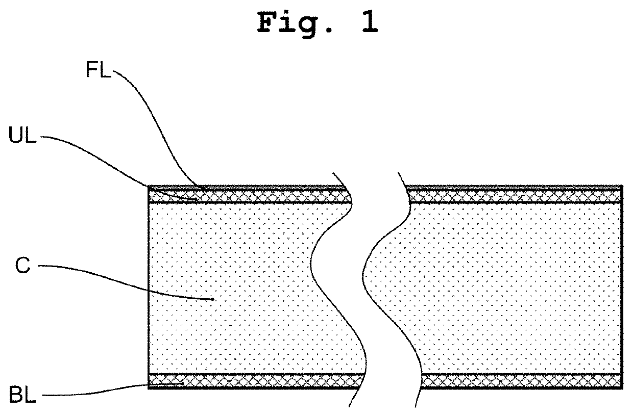
[0076]FIG. 1 depicts a floating roof according to one aspect of the present invention, comprising a bottom layer BL, a core C, and an upper layer UL arranged in a sandwich structure. In this embodiment, a fire-retardant top layer FL is provided on top of the upper layer UL, and the upper layer UL serves as substrate for the fire-retardant top layer (FL).

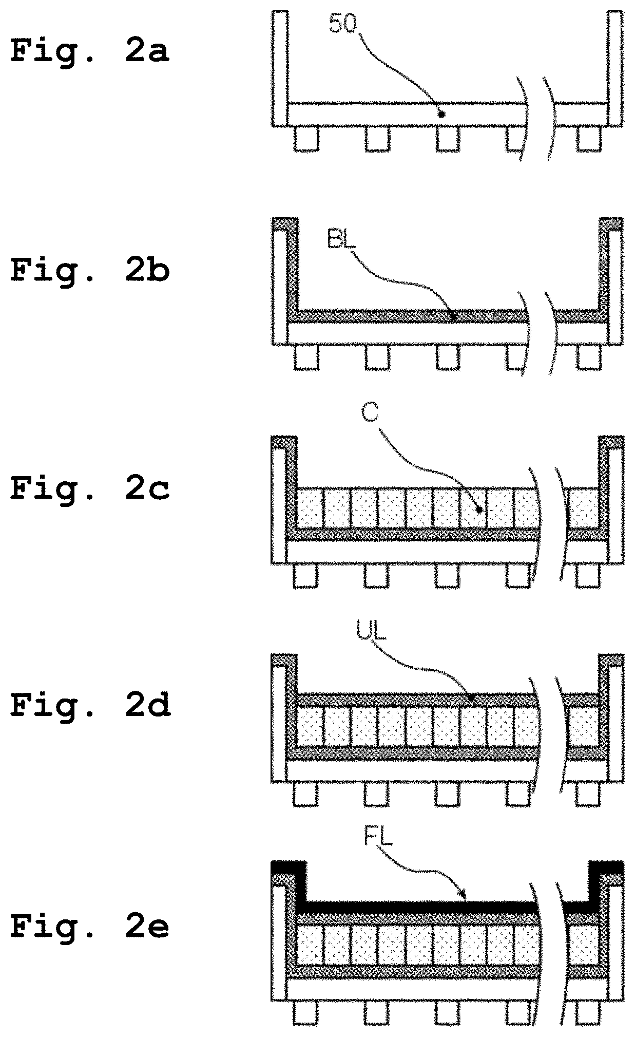
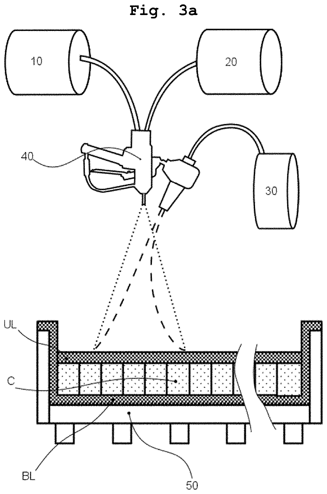
[0077]The steps for manufacturing a floating roof according to one embodiment of the present invention are depicted in FIG. 2a to FIG. 2f. First a mold 50 is constructed within the interior of a tank (not shown), see FIG. 2a. The mold is typically constructed from melamine coated boards. The mold comprises a flat upper surface and a circumferential sidewall inside the tank. To ensure that the top surface of the mold has an even structure and that no resin can flow through the gaps between the boards, tapes (not shown) may be provided to cover the gaps.

[0078]Then the bottom layer BL made from a fiber-reinforced resin material is provi...


PUM

PropertyMeasurementUnit
lengthaaaaaaaaaa
lengthaaaaaaaaaa
volume resistivityaaaaaaaaaa

Abstract

The present invention relates to floating roofs for tanks that are used for storage of flammable liquids, such as petroleum or refinery products such as diesel, kerosene, gasoline, etc. In one aspect, the present invention concerns a method for forming a fire retardant coating of a floating roof, and a floating roof obtainable thereby. In another aspect, the present invention relates to improvements in structure of a floating roof. The floating roof tank may be a seamless composite floating roof tank for refineries.

Description

TECHNOLOGICAL FIELD[0001]The present invention generally relates to floating roofs for tanks that are used for storage of flammable liquids, such as petroleum or refinery products such as diesel, kerosene, gasoline, etc. In one aspect, the present invention concerns a method for forming a fire retardant coating of a floating roof, and a floating roof obtainable thereby. In another aspect, the present invention relates to improvements in structure of a floating roof. The floating roof tank may be a seamless composite floating roof tank for refineries.BACKGROUND[0002]Large storage tanks for refineries typically store volatile and flammable liquids like gasoline, naphtha, kerosene, diesel, and crude oil. Evaporative losses are a concern for such storage tanks, as they are economically and environmentally undesirable. In order to minimize or avoid the formation of a vapor phase above the liquid level and to thereby minimize evaporative loss, a floating roof can be used. Floating roofs a...

Claims


Application Information

Patent Timeline
Patent Type & Authority Applications(United States)
IPC IPC(8): B65D88/34A62C3/06B32B27/18B32B5/18C08J5/04C08J7/05C08J7/06B32B27/28C08K3/40C08K7/14
CPCB65D88/34C08J2367/06B32B27/18B32B5/18C08J5/043C08J7/05C08J7/06B32B27/285C08K3/40C08K7/14B32B2250/40B32B2255/102B32B2262/101B32B2262/105B32B2264/108B32B2266/0264B32B2307/3065B32B2307/72B32B2419/06B32B2435/02A62C3/065C08J2331/02C08J2363/00C08J2367/00B32B2262/106C08J5/0405
Inventor HAJNAJ, JOANNA
Owner ENVIRONMENTAL PROTECTION TECH FOR STORAGE TANKS GMBH
Learn More