[0015] Furthermore, since the indentations are arranged vertically, even when toner drops from above, the upper side indentation acts as a roof so that the toner is prevented from directly dropping on the space between the indentations, and it is difficult for the translucent windows of the indentations become smeared. In this way, it is possible to always accurately determine the remaining toner. Furthermore, since toner does not drop directly on the space between the indentations, the level of toner is kept stable in this space and it is possible to carry out very accurate determinations of the remaining toner.
[0017] In this case, it is possible to remove smearing from the translucent windows of the indentations and always accurately determine the remaining toner.
[0025] In this case, since the sweeping member is film with flexibility, when there is sufficient toner, the sweeping member is immersed, receives large resistance and bends in shape, and when there is little toner, the shape of the member recovers. Using this, when there is sufficient toner, the sweeping member is hindered from approaching the translucent windows of the indentations due to the
shape change of the sweeping member, thus preventing the occurrence of abrasions to the surfaces of the translucent windows of the indentations due to
sliding contact with the sweeping member. And when there is little toner, the sweeping member slides in contact with surfaces of the translucent windows of the indentations due to the recover of shape of the sweeping member, and the surfaces of the translucent windows of the indentations can be swept by the
sliding contact with the sweeping member. Furthermore, if the sweeping member is a flexible film, even when the sweeping member slides in contact with the surfaces of the translucent windows of the indentations, these surfaces of the translucent windows are only lightly rubbed, and it is difficult to abrade the surfaces of the translucent windows. Furthermore, if the sweeping member is a flexible film, there is little friction between the sweeping member and the surfaces of the translucent windows of the indentations. For this reason, if the sweeping member is made to operate together with the agitation movement of the
agitator member, it is possible to suppress increases to the load applied to the
agitator member and there is no unevenness in the agitation movement of the
agitator member.
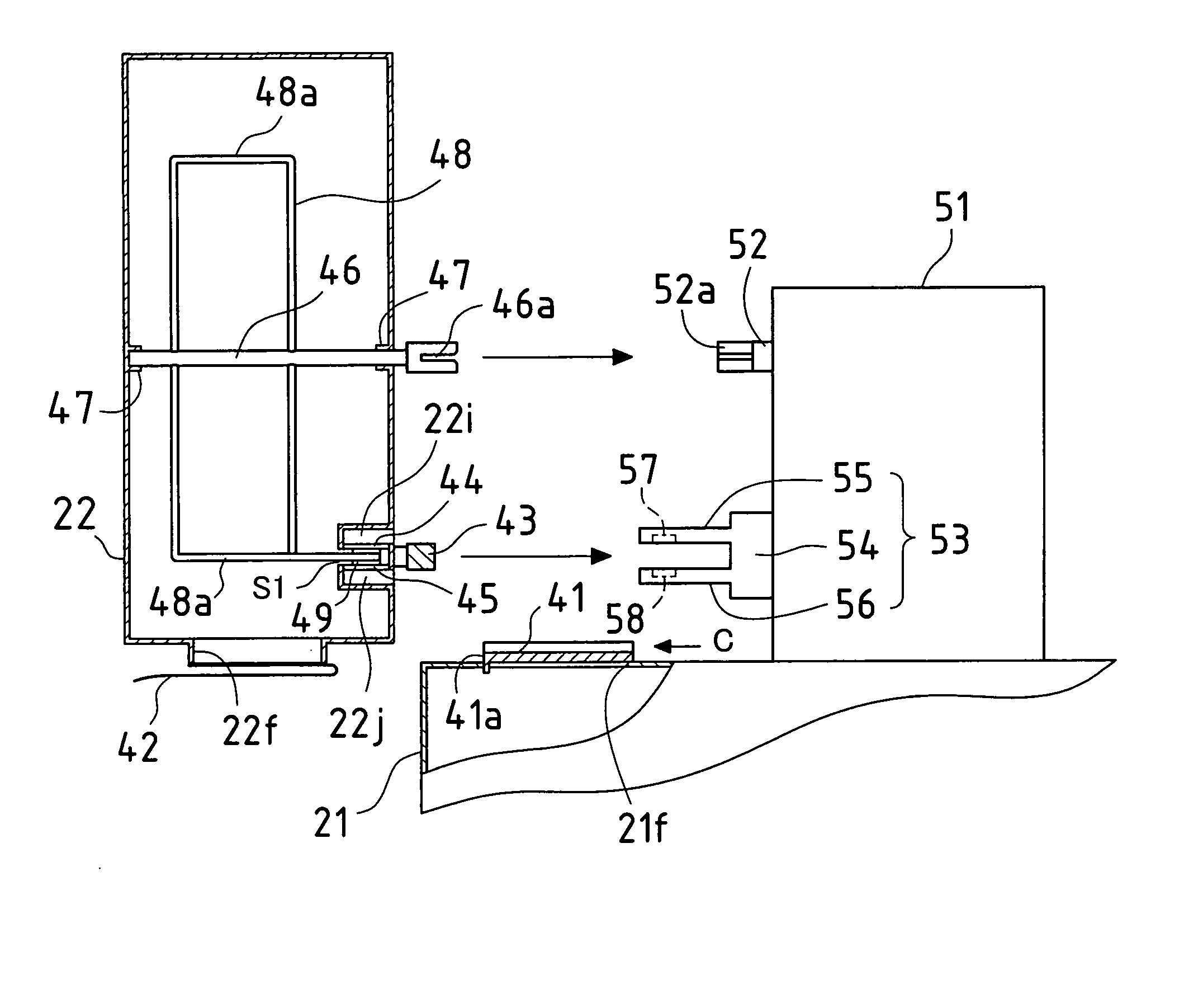
[0027] In this case, since the depth of the toner cartridge is set shorter than the depth of the developing device in an image forming apparatus, it is easy to make uniform the toner in the toner cartridge using agitation of the agitator member, and this reduces deviation in the toner, thus making it possible to carry out accurate determination of the remaining toner. Furthermore, since the height of the toner cartridge is set longer than the depth of the toner cartridge, the capacity of the toner cartridge can be maintained. It should be noted that, when comparing the depth of the toner cartridge and the depth of the developing device, it is preferable for the depth of the toner cartridge to be sufficiently shorter than the depth of the developing device.
[0033] According to the present invention, regardless of the arrangement state of the light-emitting face of the light-emitting element and the light-receiving face of the light-receiving element, the flexible film is made to pass through the vicinity of the light-emitting face and the light-receiving face such that the light-emitting face and the light-receiving face are swept by the flexible film. The flexible film lightly rubs the light-emitting face and the light-receiving face and removes smearing from the light-emitting face and the light-receiving face without causing abrasion to the light-emitting face and the light-receiving face.
[0035] In the present invention, since is it possible to bring the toner cartridges close to the front door, it is also possible to achieve
miniaturization of an image forming apparatus. In particular, if a height h of the toner cartridge is set longer than a depth t of the toner cartridge and thus making the width of the toner cartridge even narrower, the toner cartridge can be miniaturized such that the image forming apparatus can also be further miniaturized.

