Positioning system for moving a selected station of a holding plate to a predetermined location for interaction with a probe

a technology of positioning system and holding plate, which is applied in the field of positioning system for moving a selected station of a holding plate to a predetermined location for interaction with a probe, can solve the problems of manual alignment of a selected station with a probe, and affecting the operation of the holding pla

Inactive Publication Date: 2005-06-02
DIVERSA
View PDF1 Cites 3 Cited by
  • Summary
  • Abstract
  • Description
  • Claims
  • Application Information

AI Technical Summary

Benefits of technology

[0013] In operation, the device is initially calibrated (calibration procedure described below). Next, a first holding plate is installed on the stage, placing the holding plate at a first location in the mxy plane. The expectation at this point is that there will be an optical contrast between various stations in the holding plate. One or more pixel images are then obtained by the camera that images the array of stations positioned at the first location in the mxy plane and the projection of the probe in the mxy plane. For the present invention, the pixel image defines a coordinate plane (pxy) that is related to the coordinate plane (mxy). From the pixel image, the operator selects a specific station of the holding plate that requires interaction with the probe. This information is then transferred to t he computer processor. The computer processor instructs the motorized linear actuators to

Problems solved by technology

Unfortunately, for stations having extremely small diameters, such as through-holes with diameters of 500 microns or less, it is impossible for all practical purposes, to manually align a selected station with a probe.
Unfortunately, due to defects in the manufacturing processes that are used to prepare the holding plates, the axes of the stations can sometimes

Method used


Image

  • Positioning system for moving a selected station of a holding plate to a predetermined location for interaction with a probe
  • Positioning system for moving a selected station of a holding plate to a predetermined location for interaction with a probe
  • Positioning system for moving a selected station of a holding plate to a predetermined location for interaction with a probe

Examples


Embodiment Construction

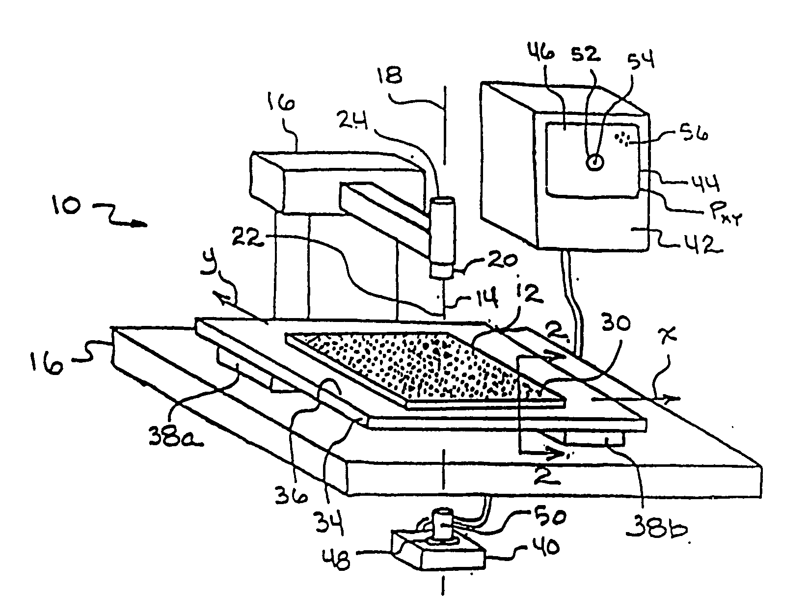
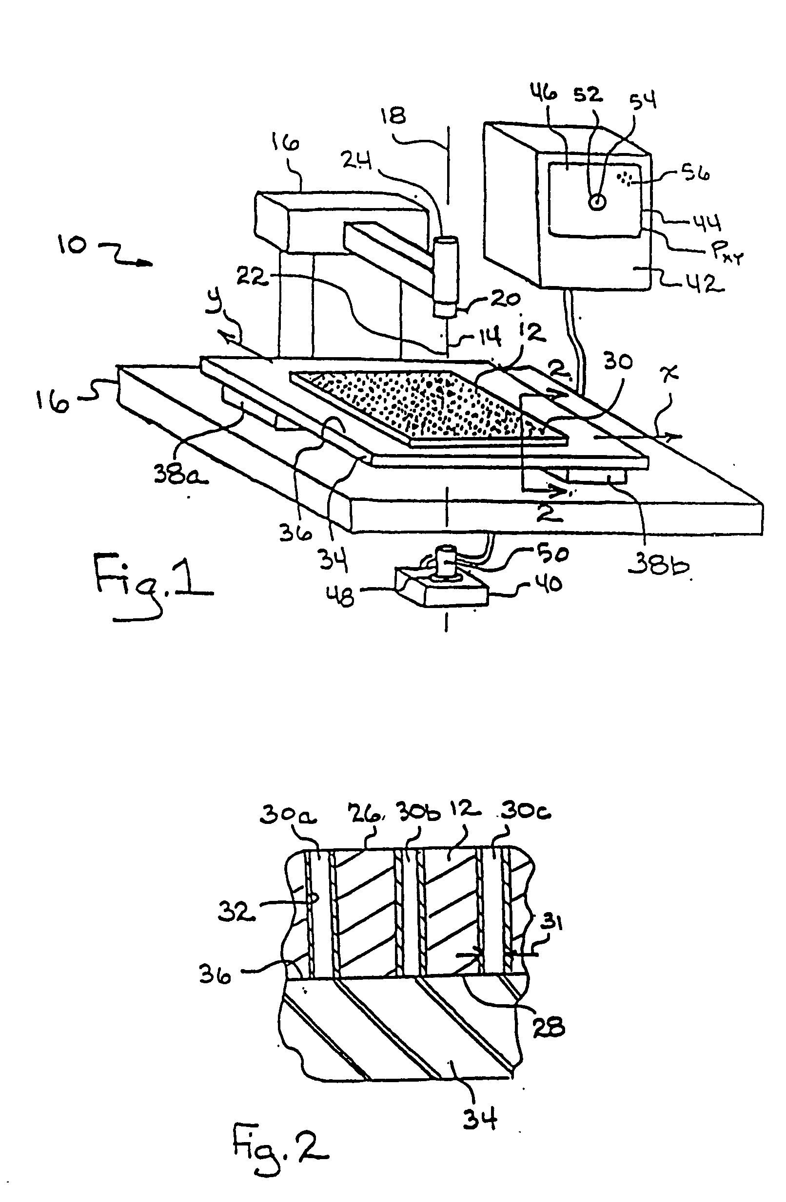
[0022] Referring initially to FIG. 1, a system 10 for performing operations on selected samples in a holding plate 12 with a probe 14 in accordance with the present invention is shown. As shown, the system 10 includes a base 16 for supporting both the holding plate 12 and the probe 14. As further shown, the probe 14 is preferably elongated and defines a probe axis 18 in the direction of elongation. In the preferred embodiment of the present invention, the probe 14 is formed as a hollow needle having a lumen capable of transferring fluid. Also shown in FIG. 1, the elongated probe 14 is preferably mounted on a hub 20 and extends from the hub 20 to a probe tip 22. For the present invention, the hub 20, which is preferably fluorescent, is somehow optically distinguishable from the probe 14. The system 10 also includes a mechanism 24 to move the probe 14 back and forth along the probe axis 18, relative to the base 16 and holding plate 12. Those skilled in the art will appreciate that any...


PUM

PropertyMeasurementUnit
Thicknessaaaaaaaaaa
Angleaaaaaaaaaa
Fluorescenceaaaaaaaaaa

Abstract

A device for positioning the tip of an elongated probe (14) at a selected station of a holding plate (12) includes motors to move the holding plate and a supporting stage within a coordinate plane (mxy). The elongated probe is also movable along a linear probe axis that is orientated normal to the coordinate plane (mxy). A camera creates a pixel image of an optical marker placed on the stage. The image defines a coordinate plane (pxy). To relate the coordinate plane (pxy) to the coordinate plane (mxy), the optical marker is moved to successive locations in the mxy plane and a pixel image is obtained at each location. Using the pixel images, a computer calculates the relationship between coordinate planes and uses the relationship to signal the motors to move the holding plate in the mxy plane and position the selected station on the probe axis for interaction with the probe.

Description

[0001] The present application is a continuation-in-part of pending U.S. patent application Ser. No. 09 / 894,956 filed Jun. 27, 2001, which is a continuation-in-part of pending U.S. patent application Ser. No. 09 / 687,219, filed Oct. 12, 2000, which is a continuation-in-part of pending U.S. patent application Ser. No. 09 / 444,112, filed Nov. 22, 1999, which is a continuation-in-part of pending U.S. patent application Ser. No. 08 / 876,276, filed Jun. 16, 1997; additionally, the present application is a continuation-in-part of pending U.S. patent application Ser. No. 09 / 636,778, filed Aug. 11, 2000, which application is a continuation and claims the benefit of priority under 35 U.S.C. § 120 of U.S. patent application Ser. No. 09 / 098,206, filed Jun. 16, 1998, which issued as U.S. Pat. No. 6,174,673 on Jan. 16, 2001, which is a continuation-in-part of pending U.S. patent application Ser. No. 08 / 876,276, filed Jun. 16, 1997, all of the contents of which are incorporated by reference in their...

Claims


Application Information

Patent Timeline
IPC IPC(8): A61B6/00C12M1/34C12Q1/68G01N21/03G06K9/00
CPCG01N21/0303
Inventor LAFFERTY, WILLIAM MICHAEL
Owner DIVERSA
Why Eureka
Try Eureka