Method and apparatus for positioning an object with respect to the isocenter of an acquisition system

Active Publication Date: 2005-06-02
STRYKER EURO OPERATIONS HLDG LLC
View PDF9 Cites 25 Cited by
  • Summary
  • Abstract
  • Description
  • Claims
  • Application Information

AI Technical Summary

Problems solved by technology

For instance, internal defects in an object may be detected.
Additionally, health and safety standards limit radiation dosage

Method used


Image

  • Method and apparatus for positioning an object with respect to the isocenter of an acquisition system
  • Method and apparatus for positioning an object with respect to the isocenter of an acquisition system
  • Method and apparatus for positioning an object with respect to the isocenter of an acquisition system

Examples


Embodiment Construction

[0019] For illustration purposes only, certain embodiments of the present invention are described in relation to an x-ray imaging system. Embodiments of the present invention may apply to a plurality of modalities, such as magnetic resonance (MR) imaging, x-ray imaging, computed tomographic (CT) imaging, electron beam tomographic (EBT) imaging, positron emission tomographic (PET) imaging, single photon emission computed tomographic (SPECT) imaging, and ultrasound imaging.

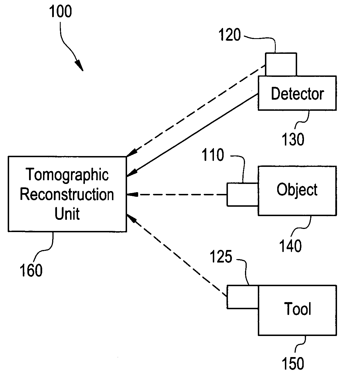
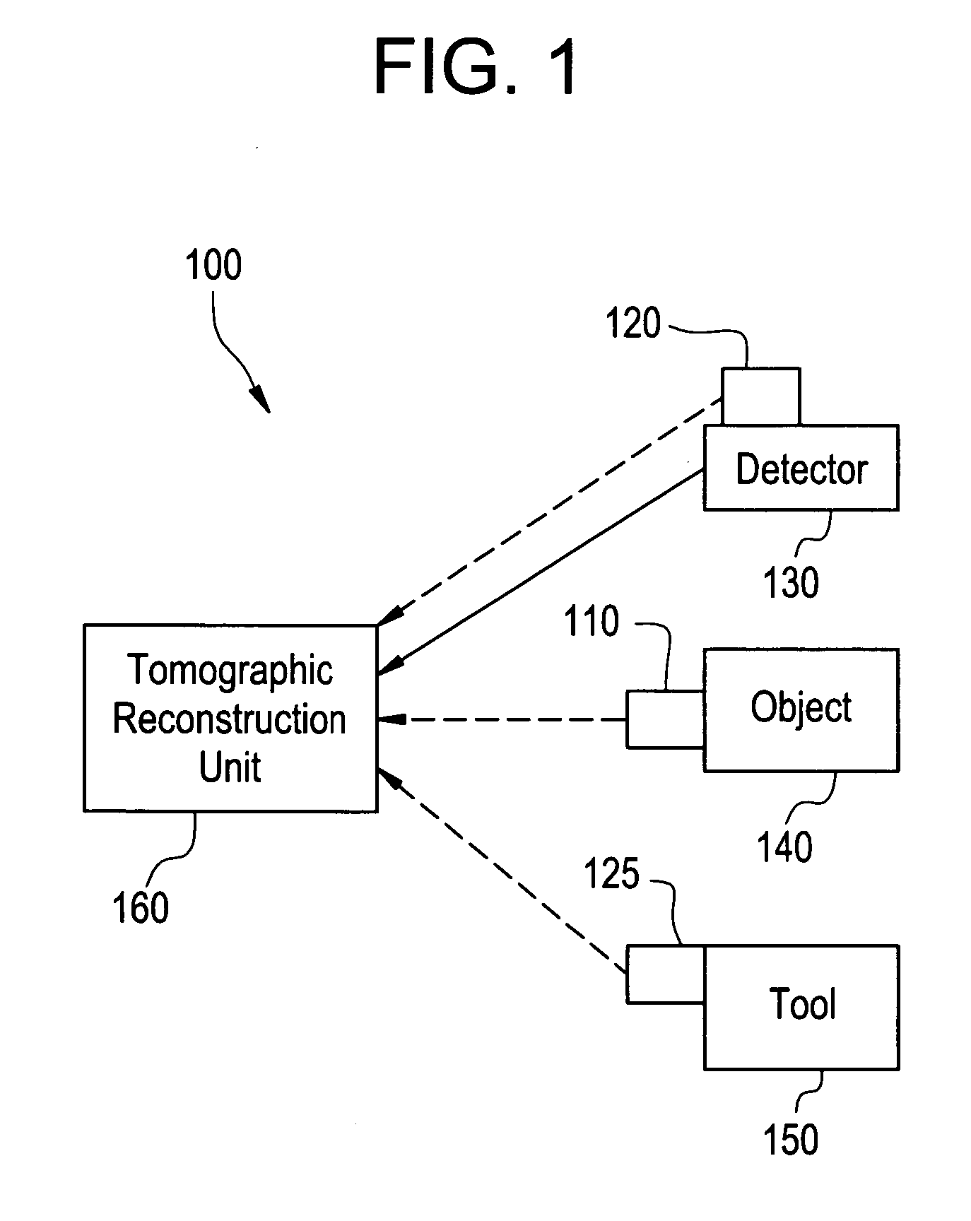
[0020]FIG. 1 illustrates an object positioning system 100 for x-ray imaging used in accordance with an embodiment of the present invention. The system 100 includes an electromagnetic (EM) emitter 110, EM receivers 120, 125, an x-ray detector 130, an x-ray source 135, an object 140, a tool 150, and a tomographic reconstruction unit 160. The EM emitter 110 is attached to the object 140. The EM receiver 120 is attached to the x-ray detector 130. The EM receiver 125 is attached to the tool 150.

[0021] The EM emitter 11...


PUM


Abstract

Certain embodiments of the present invention relate to a system and method for object and isocenter alignment in an imaging system. The system includes an electromagnetic, an electromagnetic receiver, and an imaging unit for determining an isocenter of an imaging scanner based on information from the electromagnetic receiver. The imaging unit identifies the isocenter based on a plurality of electromagnetic position measurements. The imaging unit identifies a center of an object to be imaged based on information from a second electromagnetic receiver. The imaging unit repositions the object based on the isocenter. In an embodiment, the emitter is located on the object, the first receiver is located on a detector, and the second receiver is located on a tool for identifying a center of the object or a portion of the object.

Description

BACKGROUND OF THE INVENTION [0001] The present invention generally relates to object positioning for image acquisition. In particular, the present invention relates to object positioning with respect to the isocenter of an acquisition system for image acquisition. [0002] Medical diagnostic imaging systems encompass a variety of imaging modalities, such as x-ray systems, computerized tomography (CT) systems, ultrasound systems, electron beam tomography (EBT) systems, magnetic resonance (MR) systems, and the like. Medical diagnostic imaging systems generate images of an object, such as a patient, for example, through exposure to an energy source, such as x-rays passing through a patient, for example. The generated images may be used for many purposes. For instance, internal defects in an object may be detected. Additionally, changes in internal structure or alignment may be determined. Fluid flow within an object may also be represented. Furthermore, the image may show the presence or...

Claims


Application Information

Patent Timeline
IPC IPC(8): A61B6/00A61B5/05A61B5/055A61B6/02A61B6/03A61B6/04A61B6/08A61B8/00A61B19/00A61N5/10G01N23/04G06T11/00
CPCA61B5/1127A61B6/547A61B6/08
Inventor PESCATORE, JEREMIE
Owner STRYKER EURO OPERATIONS HLDG LLC
Why Eureka
Try Eureka