
Electrochemical cell cooling system

a technology of electrochemical cells and cooling systems, applied in the field of electrochemical cell cooling systems, can solve the problems of venturi inducing a negative pressure condition in the container and loop, and achieve the effect of efficient and cost-effective cooling and simple and efficient cooling

Inactive Publication Date: 2005-06-09
GREENLIGHT POWER TECH
View PDF7 Cites 12 Cited by
  • Summary
  • Abstract
  • Description
  • Claims
  • Application Information

AI Technical Summary

Benefits of technology

[0009] It is therefore an object of the invention to provide a simplified cooling system that can provide an electrochemical cell with both positive and negative coolant pressure conditions in an efficient manner.
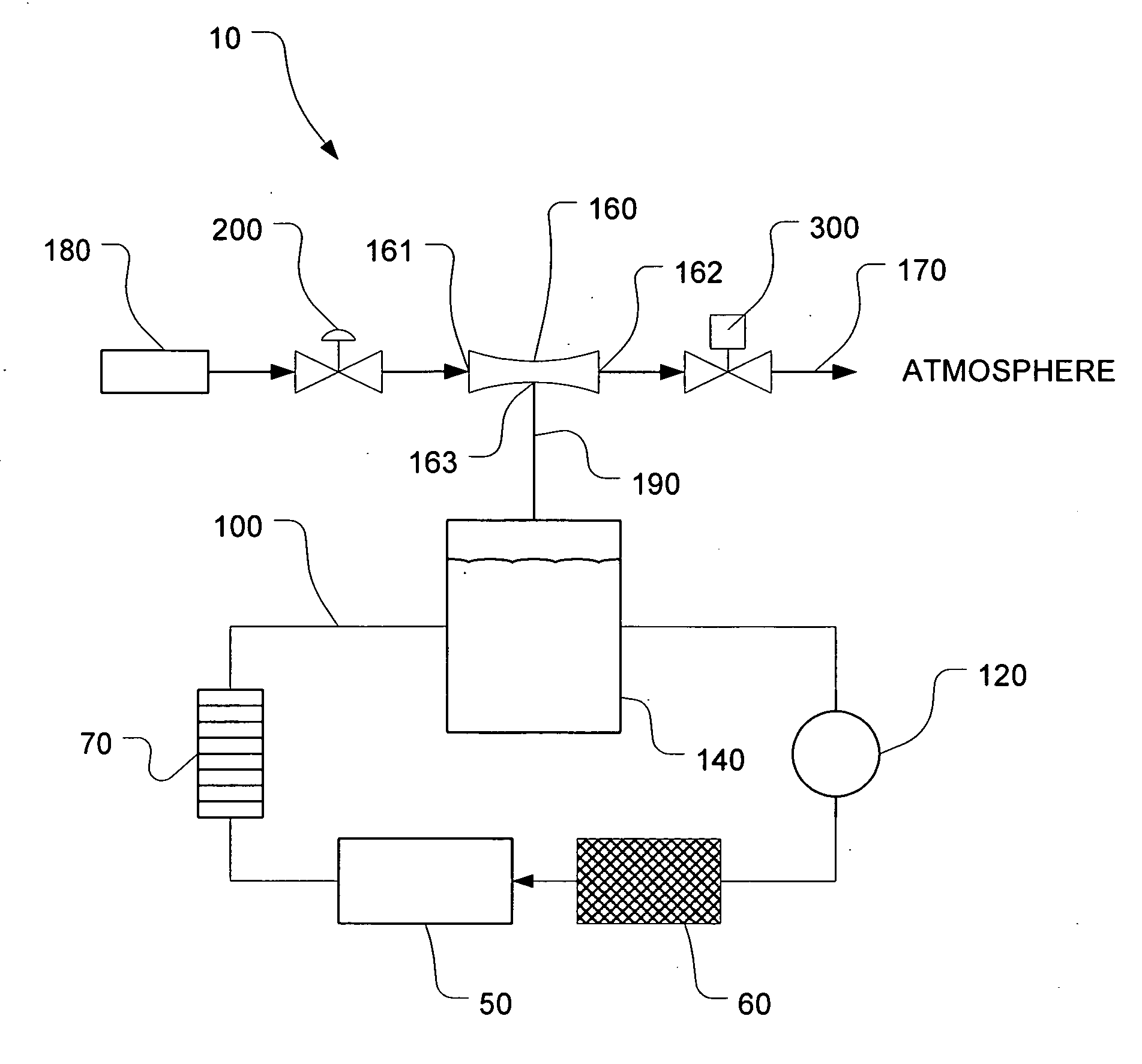
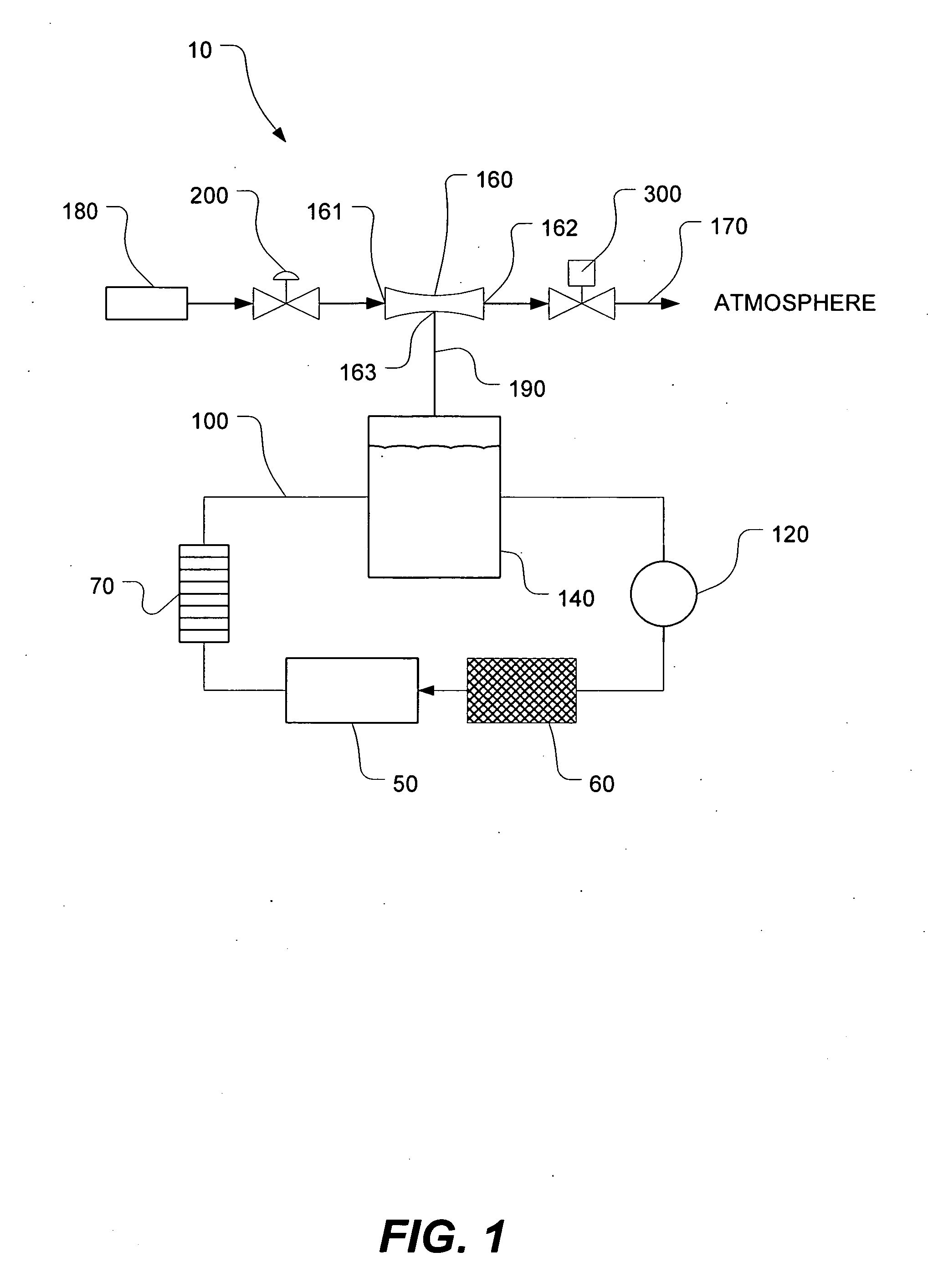
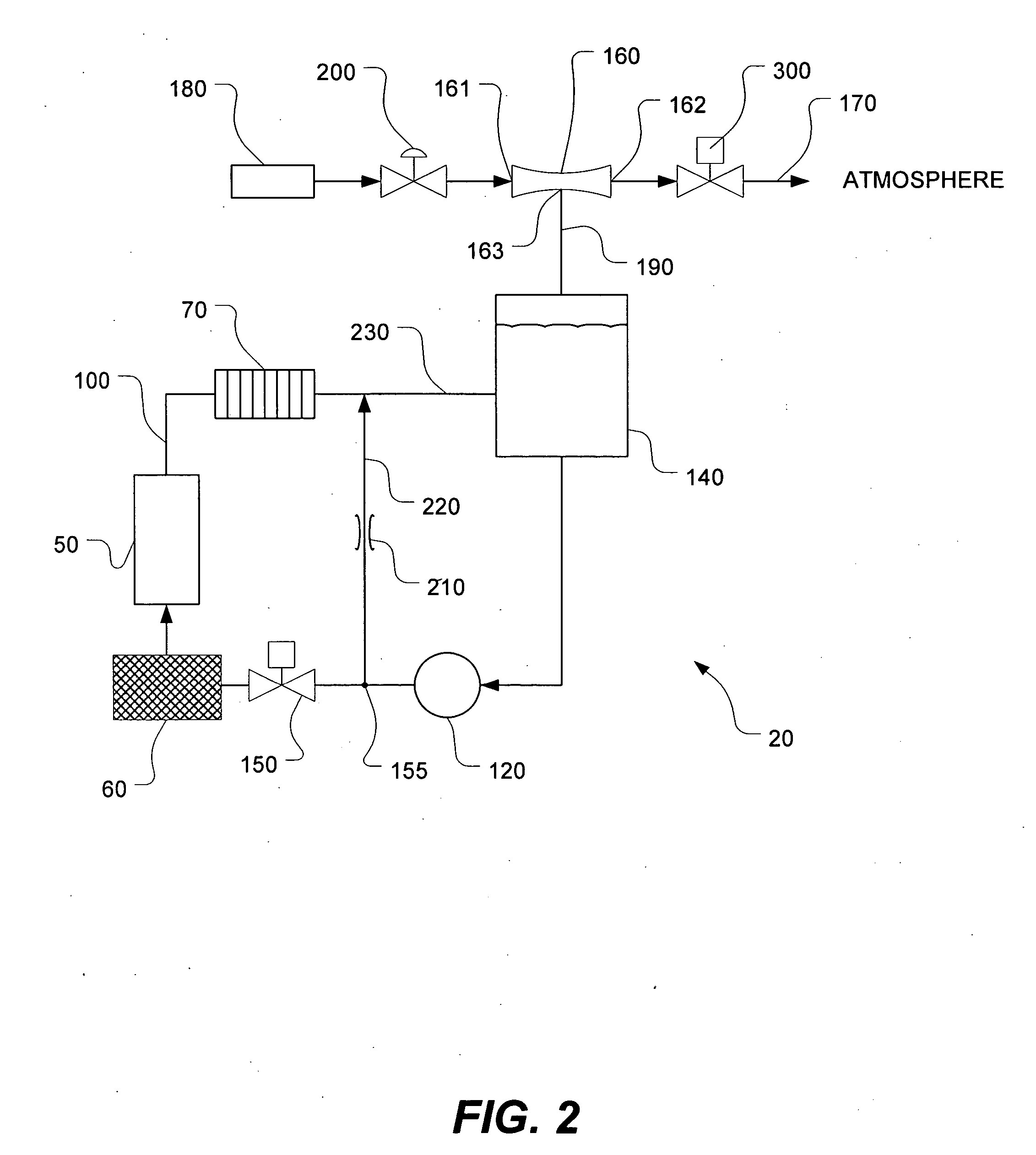
[0011] In one embodiment, the flow line includes a venturi in fluid communication with the container and a shut-off valve downstream of the venturi for selectively pressurizing or depressurizing the container and loop. When the shut-off valve is open, the fluid flows through an inlet and outlet of the venturi and exhausts to atmosphere, causing the venturi to induce a negative pressure condition in the container and loop. When the shut-off valve is closed, the fluid is forced to flow through a bottom port of the venturi into the container, thus causing a positive pressure condition in the loop. As a refinement, a variable-flow valve can be provided upstream of the venturi to regulate the fluid pressure in the flow line, thus enabling fine adjustment of the pressurization or depressurization of the container and loop. As a further refinement, a bypass with a flow constriction can be provided to facilitate coolant temperature control.
[0019] The present invention thereby provides a system and method for simple and efficient cooling of an electrochemical cell under either positive or negative coolant pressure conditions. This invention therefore enables efficient and cost-effective cooling of electrochemical cells, such as those utilized in fuel cell stacks.

Problems solved by technology

When the shut-off valve is open, the fluid flows through an inlet and outlet of the venturi and exhausts to atmosphere, causing the venturi to induce a negative pressure condition in the container and loop.

Method used


Image

  • Electrochemical cell cooling system
  • Electrochemical cell cooling system
  • Electrochemical cell cooling system

Examples


Embodiment Construction

[0024]FIG. 1 shows, in schematic form, an electrochemical cell cooling system, generally designated by reference numeral 10, in accordance with a first embodiment of the present invention. Although the present invention can be used to efficiently cool fuel cell systems, it is not limited to application in fuel cell systems. Rather, it is applicable to any electrochemical cell system where liquid coolant is needed to control the operating temperature of the electrochemical cell.

[0025] As shown in FIG. 1, the cooling system 10 includes a coolant circulation loop 100 for circulating a coolant through or past an electrochemical cell 50 for absorbing heat from the exothermic reaction of a working electrochemical cell 50. The coolant circulation loop 100 includes a coolant container 140, which is also known as an overflow tank or storage tank. The coolant container 140 stores an excess volume of coolant at a nominal operating pressure, which can be adjusted in a manner to be described be...


PUM


Abstract

An electrochemical cell cooling system includes a closed loop for circulating coolant through an electrochemical cell. The loop includes a pump for pumping the coolant from a container through a filter and a heat exchanger. Pressure in the container and loop is selectively adjusted upwardly for a positive pressure condition or downwardly for a negative pressure condition using a pressure-adjusting flow line. The flow line includes a venturi in fluid communication with the container and a shut-off valve downstream of the venturi which is opened to induce depressurization of the loop or closed to cause pressurization. A variable-flow valve upstream of the venturi enables fine adjustment of the pressurization or depressurization. Alternatively, a flow-restricted bypass and a second variable-flow valve can be introduced to facilitate coolant temperature control.

Description

CROSS-REFERENCE TO RELATED APPLICATIONS [0001] This application claims priority from U.S. Provisional Patent Application Ser. No. 60 / 516,285 filed Nov. 3, 2003.FIELD OF THE INVENTION [0002] The present invention relates generally to an electrochemical cell system and, more particularly, to a cooling system for an electrochemical cell system. BACKGROUND OF THE INVENTION [0003] A fuel cell is an electrochemical device that produces an electromotive force by bringing the fuel (typically hydrogen) and an oxidant (typically air) into contact with two suitable electrodes and an electrolyte. A fuel, such as hydrogen gas, for example, is introduced at a first electrode where it reacts electrochemically in the presence of the electrolyte to produce electrons and cations in the first electrode. The electrons are circulated from the first electrode to a second electrode through an electrical circuit connected between the electrodes. Cations pass through the electrolyte to the second electrode....

Claims


Application Information

Patent Timeline
IPC IPC(8): F25B19/00F25D23/12H01M8/04
CPCH01M8/04029Y02E60/50H01M8/04089
Inventor LAMONT, GORDON JOHNMARTIN, BENJAMIN WILLIAMPIOTROWSKI, JACEK
Owner GREENLIGHT POWER TECH
Learn More