Distributed sensor array for fluid contaminant monitoring

a technology of fluid contamination and sensor array, which is applied in the direction of volume metering, machines/engines, instruments, etc., can solve the problems of limited options for complying with homeland security mandate, few systems available today that provide cost effective early detection and response systems, and approaches using periodic sampling that cannot protect civilians

Inactive Publication Date: 2005-06-09
ENVIRONMENTAL SECURITY CORP
View PDF10 Cites 34 Cited by
  • Summary
  • Abstract
  • Description
  • Claims
  • Application Information

AI Technical Summary

Problems solved by technology

Yet few systems are available today that provide cost effective early-detection and response systems for warning of attacks on our water supplies.
Existing approaches using periodic sampling do not suffice to protect the civilian population from water supply contamination, leaving municipalities with few safety choices and limited options for complying with the Homeland Security mandate.
This trend may well make the western water supplies of the U.S. especially vulnerable to ter

Method used


Image

  • Distributed sensor array for fluid contaminant monitoring
  • Distributed sensor array for fluid contaminant monitoring
  • Distributed sensor array for fluid contaminant monitoring

Examples


Embodiment Construction

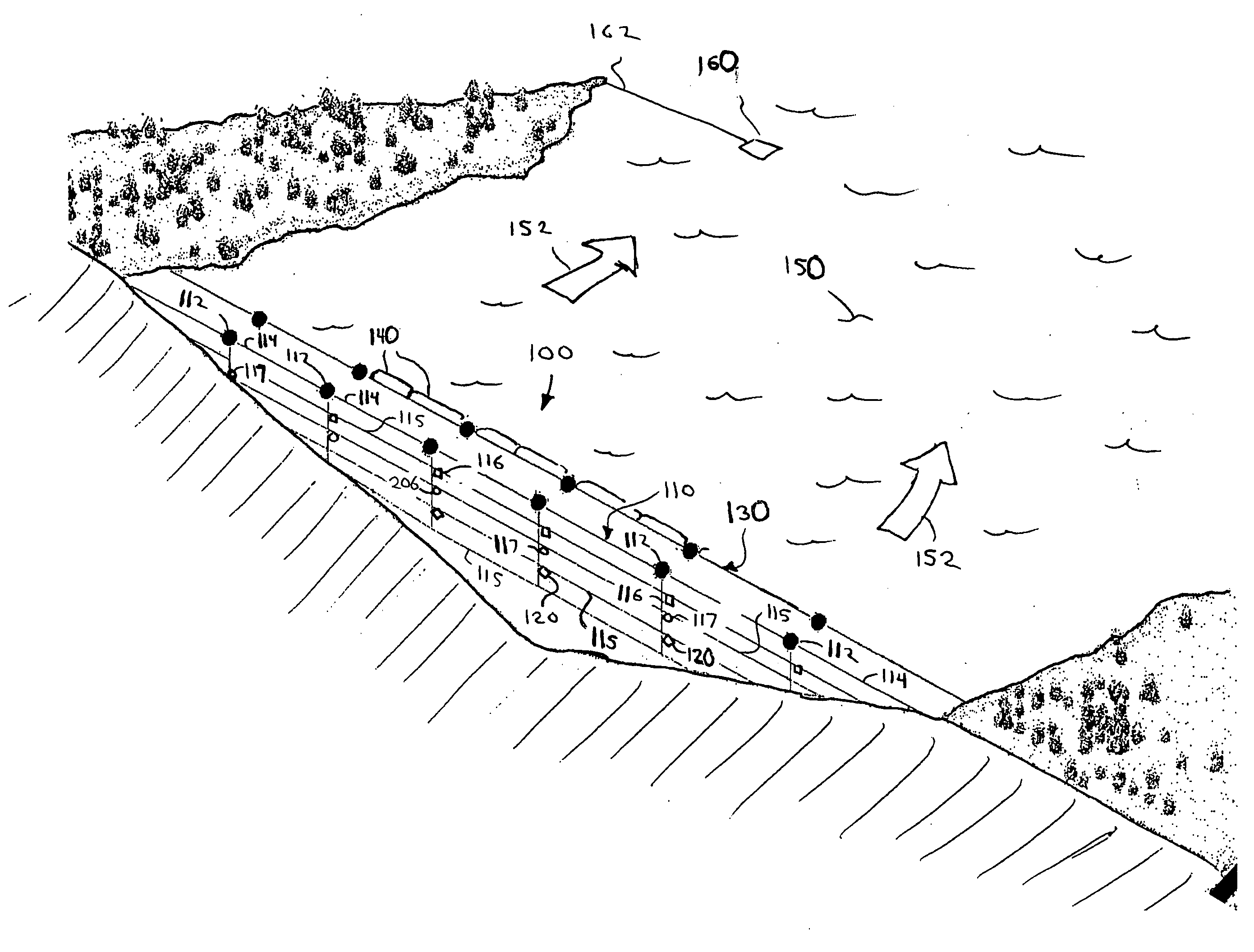
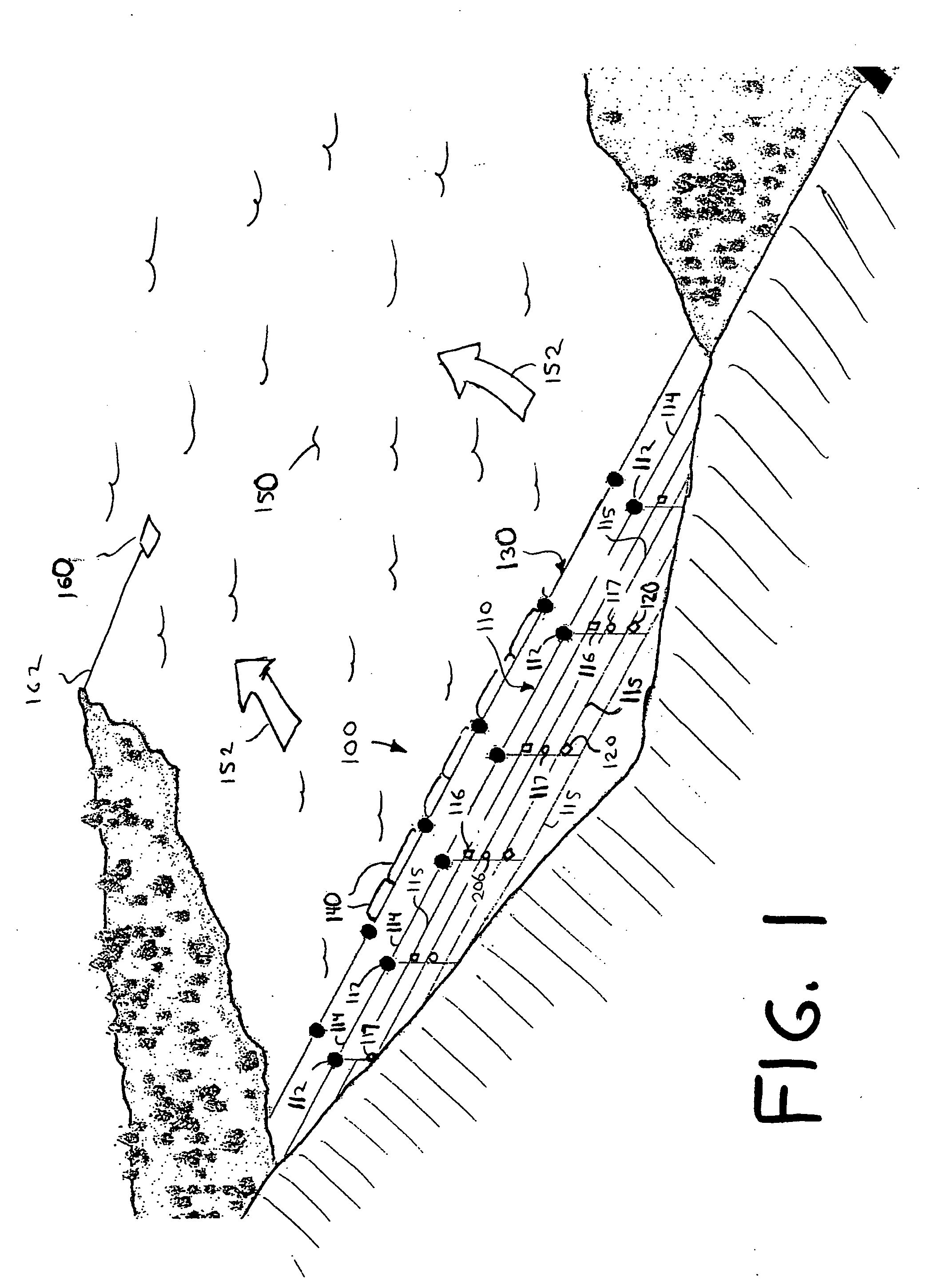
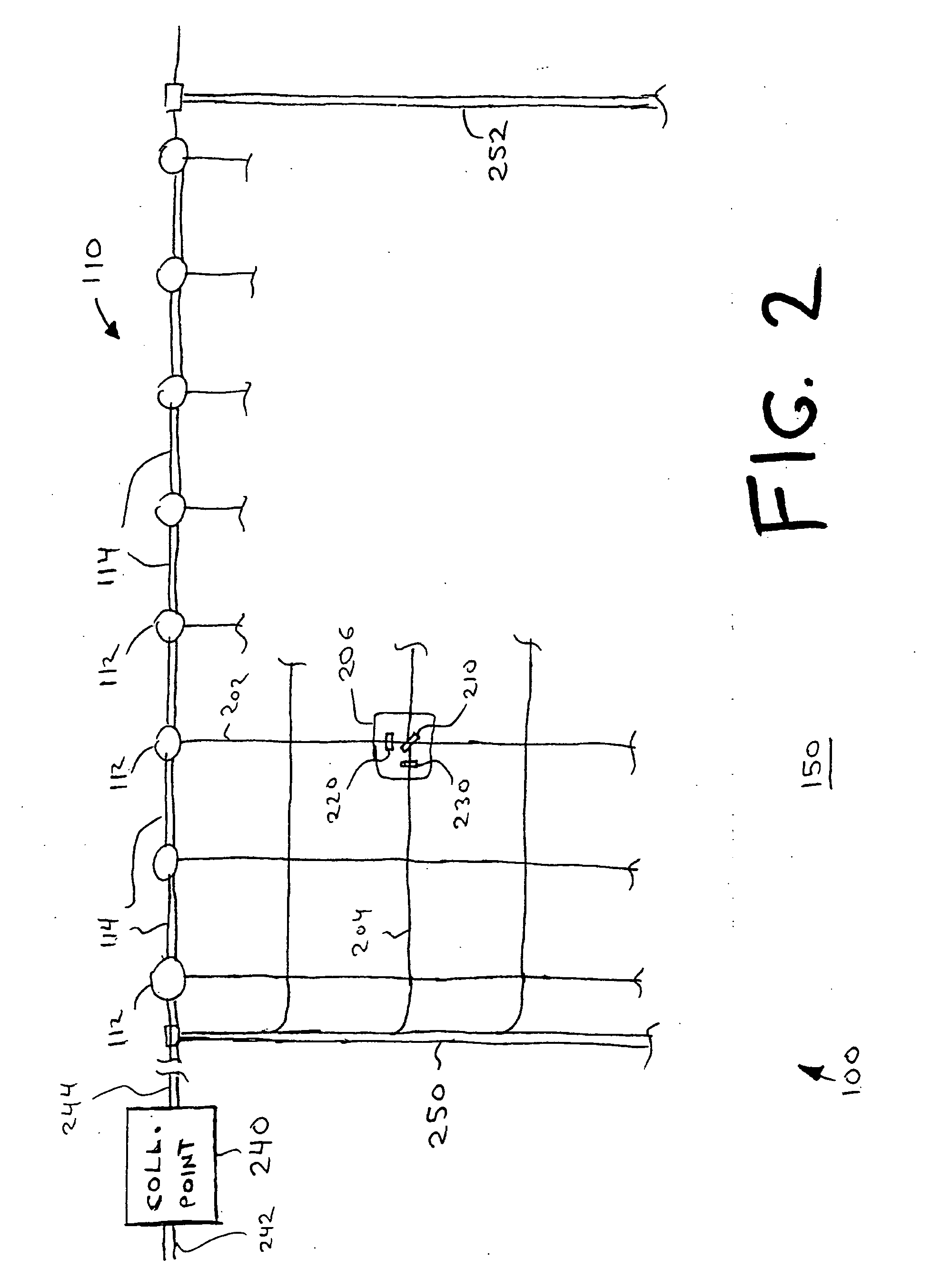
[0016] A distributed sensor array system according to various aspects of the invention provides numerous benefits including comprehensive detection of reservoir contamination. As discussed in detail below with reference to exemplary embodiments employing a single sensor array 110 (FIG. 1) and a pair of sensor arrays 510, 540 (FIG. 5), such a system transmits data representative of a level of impurities in the reservoir fluid from a number of sensors immersed in the reservoir.

[0017] Distributed sensor (i.e., detector) array system 100 of FIG. 1 is immersed in a reservoir 150 with sensor modules 112, 116, 117, 120, 206 distributed throughout a cross section of reservoir 150 from its surface to near its bottom. System 100 includes a cable network 110 of (1) horizontal cables, which include a top supporting cable 114 and subordinate cables, e.g., cable 204, and (2) crossing vertical cables, e.g., cable 202. Top supporting cable 114 connects between surface modules 112, which perform a ...


PUM


Abstract

A disclosed fluid purity monitoring system employs a network of preferably information-transmissive cables fixed in place within a body of fluid. Sensors sensitive to fluid impurities are supported at various places on the network. Data representative of impurity levels transmits to a collection point via the same cables at which the sensors are supported. One system employs at least two pluralities of sensors sensitive to different fluid impurities. Another system employs electrically conductive cables fixed in place substantially in a common plane, with some cables oriented substantially parallel to each other and intersecting other cables. In that system, the data transmits to the collection point via a separate electrical circuit for each one of the sensors. Each circuit includes a series connection of the pair of cables that intersect proximate to the sensor's support point on the network. Advantageous variations and methods are also disclosed.

Description

CROSS REFERENCE TO RELATED APPLICATIONS [0001] This application claims the benefit of, and incorporates herein by reference, U.S. provisional application Ser. No. 60 / 487,274 filed Jul. 14, 2003.BACKGROUND OF THE INVENTION [0002] Since the terrorist attacks on the United States in September 2001, a new awareness has arisen about vulnerability of drinking reservoirs to radiological, chemical, and biological threats from terrorists. The U.S. Homeland Security Department has mandated that defensive measures be taken to protect the nation's water supplies from terrorist attack. Yet few systems are available today that provide cost effective early-detection and response systems for warning of attacks on our water supplies. Existing approaches using periodic sampling do not suffice to protect the civilian population from water supply contamination, leaving municipalities with few safety choices and limited options for complying with the Homeland Security mandate. [0003] In the western U.S....

Claims


Application Information

Patent Timeline
IPC IPC(8): G01N33/00G01N33/18G06F
CPCG01N33/1806G01N33/18
Inventor VON HERZEN, BRIANRINK, GLENN R.
Owner ENVIRONMENTAL SECURITY CORP
Why Eureka
Try Eureka