Cantilever array sensor system

a sensor system and cantilever technology, applied in the field of cantilever array sensor systems, can solve the problems of increasing noise of position sensitive detectors, unable to accurately calibrate the sensitivity of detection methods, and difficulty in detecting the presence of objects, etc., to achieve accurate detection and measurement

Inactive Publication Date: 2005-06-09
PRATER CRAIG +5
View PDF12 Cites 47 Cited by
  • Summary
  • Abstract
  • Description
  • Claims
  • Application Information

AI Technical Summary

Benefits of technology

[0015] The present invention provides an integrated cantilever sensor array system that accurately detects and measures the presence of target substances in various environmental conditions.
[0018] The cantilever sensor system measures the oscillatory properties generated by the cantilevers within the cantilever array. The system includes the cantilever array and a detection system that measures a signal related to the bending of the cantilever. In addition, optional components such as a high frequency clock, Q-Control, may be added to more accurately measure the oscillation of the cantilevers within the cantilever array.
[0019] The measurement chamber includes a flow cell and a cantilever sensor array mounted within the flow cell. The flow cell is designed to minimize dead volume and unwanted air bubbles within the cell, which may reduce accuracy of measurement. In addition, the flow cell has an inlet port and an outlet port regulated by a flow control valve, which allows target substances to flow into the flow cell and contact the cantilever sensor array. The flow control permits the system to function in a static and dynamic state. In addition, a temperature control device permits the regulation and manipulation of analyte temperatures.

Problems solved by technology

It is somewhat difficult in the prior work, however, to obtain an accurate calibration of the sensitivity of the detection method.
The noise of the position sensitive detectors increase and the bandwidth decreases with increasing size.
This technique is limited by the accuracy of the feedback loop and the accuracy and speed with which the frequency can be measured.
This method has the disadvantage that a large number of periods over an extended period of time must be counted to obtain an accurate measurement.
This combined with the orientation of the inlet and outlet ports have led to large dead volumes of prior flow cells.
As a result, the molecules in the dead volume can contaminate future experiments as they diffuse out of the dead volume and into proximity of the cantilevers.
The prior flow cells also have a problem associated with the angle of the cantilevers are held with respect to the transparent window.
The problem with this arrangement is that the angle of the reflected laser beam that exits the flow cell window depends on the index of refraction of the material contained in the flow cell.

Method used


Image

  • Cantilever array sensor system
  • Cantilever array sensor system
  • Cantilever array sensor system

Examples


Embodiment Construction

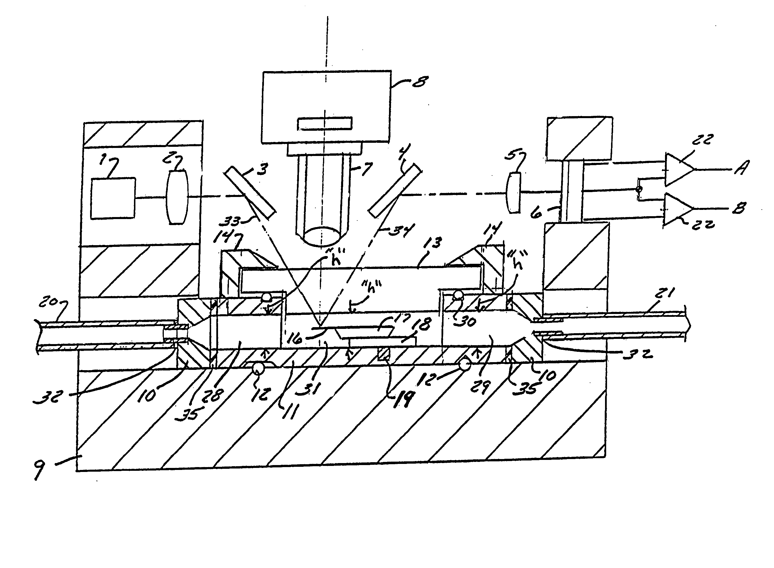
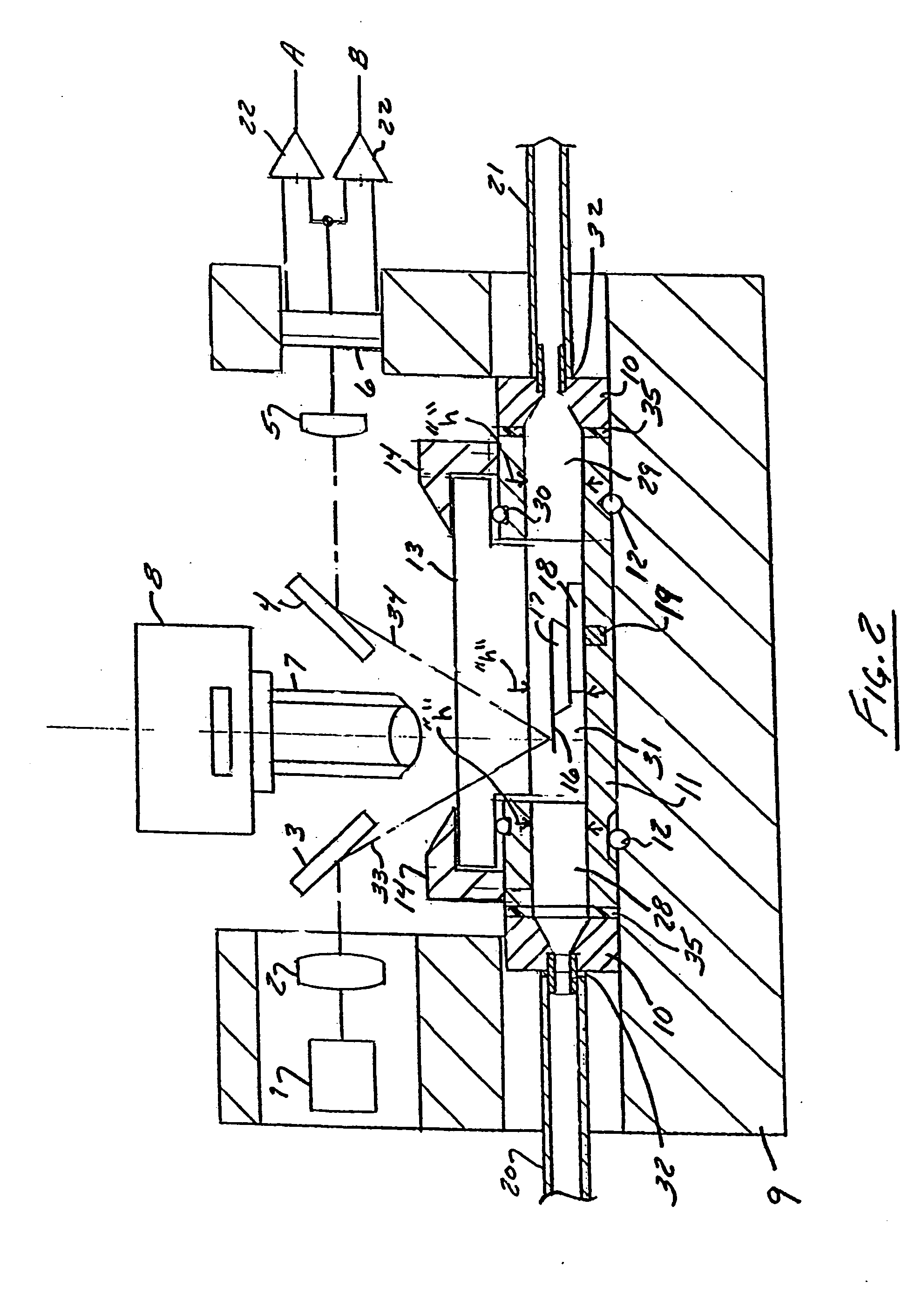
[0046] The present invention is directed toward a cantilever sensor array system comprising an integrated cantilever sensor array system comprises a cantilever sensor measurement head, a cantilever sensor system for measuring the oscillatory properties of the cantilevers and a measurement chamber and optionally, a data acquisition and control system.

[0047] The measurement head includes a cantilever array having at least one cantilever, a light source and a detector positioned to detect incoming light reflected by the cantilevers within the cantilever array. The cantilever sensor system includes the cantilever array and a detection system that measures a signal related to the bending of the cantilever. The measurement chamber includes a flow cell and a cantilever sensor array mounted within the flow cell.

[0048] The cantilever sensor array is formed of at least one micromechanical cantilever sensor. The flow cell of the present invention allows material in a gaseous, fluid or vacuum...


PUM

PropertyMeasurementUnit
angleaaaaaaaaaa
lengthsaaaaaaaaaa
lengthsaaaaaaaaaa

Abstract

An integrated cantilever sensor array system that accurately detects and measures the presence of target substances in various environmental conditions. The integrated cantilever sensor array system comprises a cantilever sensor measurement head, a cantilever sensor system for measuring the oscillatory properties of the cantilevers and a measurement chamber. The measurement head includes a cantilever array having at least one cantilever, a light source and a detector positioned to detect incoming light reflected by the cantilevers within the cantilever array. The cantilever sensor system measures the oscillatory properties generated by the cantilevers within the cantilever array. The system includes the cantilever array and a detection system that measures a signal related to the bending of the cantilever. In addition, optional components such as a high frequency clock, Q-Control, may be added to more accurately measure the oscillation of the cantilevers within the cantilever array. The measurement chamber includes a flow cell, a cantilever sensor array mounted within the flow cell. The flow cell is designed to minimize dead volume and unwanted air bubbles within the cell, which may reduce accuracy of measurement.

Description

CROSS-REFERENCE TO RELATED APPLICATION [0001] This application is based on and claims priority from U.S. Provisional Patent Application Ser. No. 60 / 244,798 which was filed on Oct. 30, 2000 and which was entitled “CANTILEVER ARRAY SENSOR SYSTEM”.BACKGROUND OF THE INVENTION [0002] 1. Field of the Invention [0003] This invention is directed to cantilever-based sensors and systems used to measure static and dynamic properties such as deflection, resonant frequency, phase, and amplitude as a function of time in response to various target substances. [0004] 2. Discussion of Related Art [0005] Micro-cantilevers or cantilevers are known in the art for use in detecting the presence of target substances. This is done by measuring a change in the cantilever's deflection, or resonant frequency, when the cantilever is exposed to a target substance. [0006] Cantilevers originally developed for atomic force microscopes have been used for a number of years as chemical sensing devices. In atomic forc...

Claims


Application Information

Patent Timeline
Patent Type & Authority Applications(United States)
IPC IPC(8): G01N9/00G01Q70/00G02B7/182
CPCB82Y35/00G02B7/1821G01N2291/0427G01N9/002
Inventor PRATER, CRAIGMEYER, CHARLES R.SU, CHANMINMASSIE, JAMES ROBERTBABCOCK, KENNETH LAWRENCETURNER, MARY GERTRUDE
Owner PRATER CRAIG
Why Eureka
Try Eureka