Permanent magnet synchronous motor

a permanent magnet, synchronous motor technology, applied in the direction of synchronous motors, magnetic circuit rotating parts, magnetic circuit shapes/forms/construction, etc., can solve the problems of complex manufacturing steps, inability to achieve efficient rotatory drive, and difficulty in assembling permanent magnet motors, so as to achieve accurate results, reduce the number of assembling, and facilitate the effect of job

Inactive Publication Date: 2005-06-09
PANASONIC CORP +1
View PDF12 Cites 8 Cited by
  • Summary
  • Abstract
  • Description
  • Claims
  • Application Information

AI Technical Summary

Benefits of technology

[0010] According to the first aspect of the present invention, the magnetic fluxes emanating from the permanent magnets will hardly leak to the outer peripheral surface of the rotor at a position adjacent opposite ends of the rotor magnetic poles and, instead leak to the outer peripheral surface of the rotor at a position adjacent a center point of the rotor magnetic poles. For this reason, the pattern of distribution of the magnetic fluxes in an air gap between the stator and the rotor represents a generally trapezoidal or sinusoidal waveform such that as compared with the rectangular waveform, the amount of change of the magnetic fluxes per unitary time increases and, therefore, the voltage induced across the winding of the stator can be increased to thereby intensify the rotor magnetic poles. Accordingly, in the practice of the present invention, to secure the required induced voltage, neither is the volume of the permanent magnets increased, nor the permanent magnets having a high residual magnetic flux density are required such as required in the prior art, thus making it possible to provide a high-performance and inexpensive self-starting synchronous motor having a required out-of-step torque and a high efficiency.
[0046] Where the permanent magnets are employed in the form of a rare earth magnet, a strong magnetic force can be obtained and both the rotor and the motor itself can advantageously manufactured in a compact size and lightweight.

Problems solved by technology

When the prior art permanent magnet motor of the type provided with the cage conductor is to be used since the conductor bars and the permanent magnets are employed as rotatory drive elements, if the conductor bars and the permanent magnets are incorrectly positioned relative to each other, a force generated from the conductor bars and a force generated by the permanent magnets will be counteracted with each other and, therefore, no efficient rotatory drive will be achieved.
Also, the permanent magnet motor provided with such a cage conductor requires a complicated and increased number of manufacturing steps since the permanent magnets and the conductor bars are provided in the rotor.

Method used


Image

  • Permanent magnet synchronous motor
  • Permanent magnet synchronous motor
  • Permanent magnet synchronous motor

Examples


first embodiment (

FIGS. 1 AND 2)

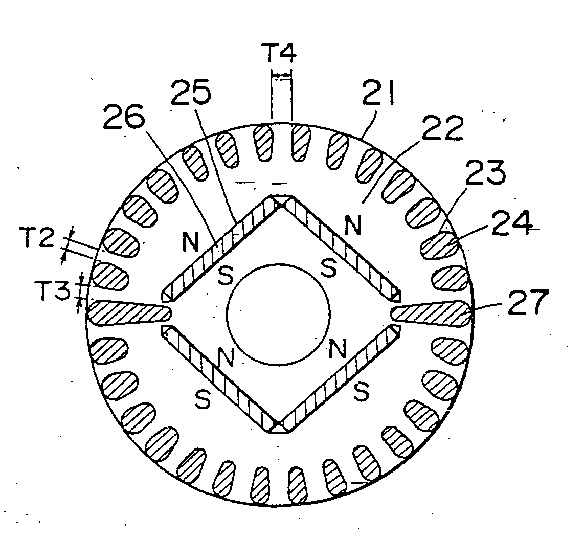
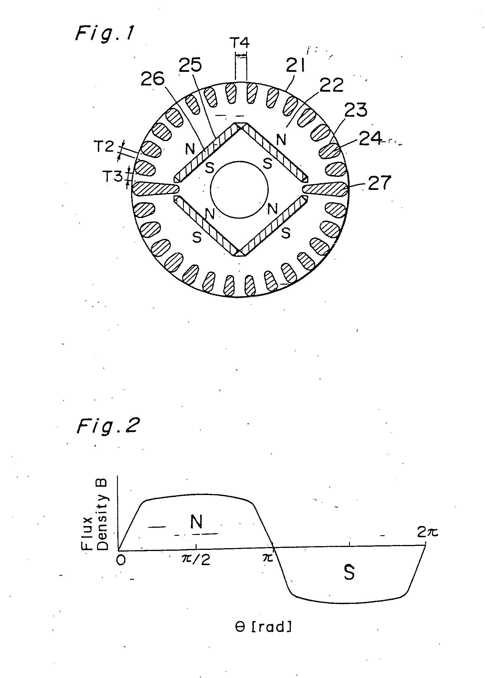
[0111]FIG. 1 illustrates a transverse sectional view of a rotor used in a self-starting synchronous motor of a type utilizing permanent magnets according to a first preferred embodiment of the present invention. In this figure, reference numeral 21 represents a rotor, and reference numeral 22 represents a rotor iron core. The rotor iron core 22 has a plurality of slots 23 defined in an outer peripheral portion thereof for accommodating a corresponding number of conductor bars 24, which are integrally molded together with shortcircuit rings (not shown) at axially spaced opposite ends of the rotor iron core 22 by the use of any known aluminum die casting to thereby provide a starter squirrel cage conductor. Permanent magnets 26 are embedded in respective magnet retaining holes defined in the rotor iron core 23 at a location radially inwardly of a round row of the conductor bars 24.

[0112] So far shown in FIG. 1, two plate-like permanent magnets 26 are butted end-to-end i...

second embodiment (fig.3)

SECOND EMBODIMENT (FIG. 3)

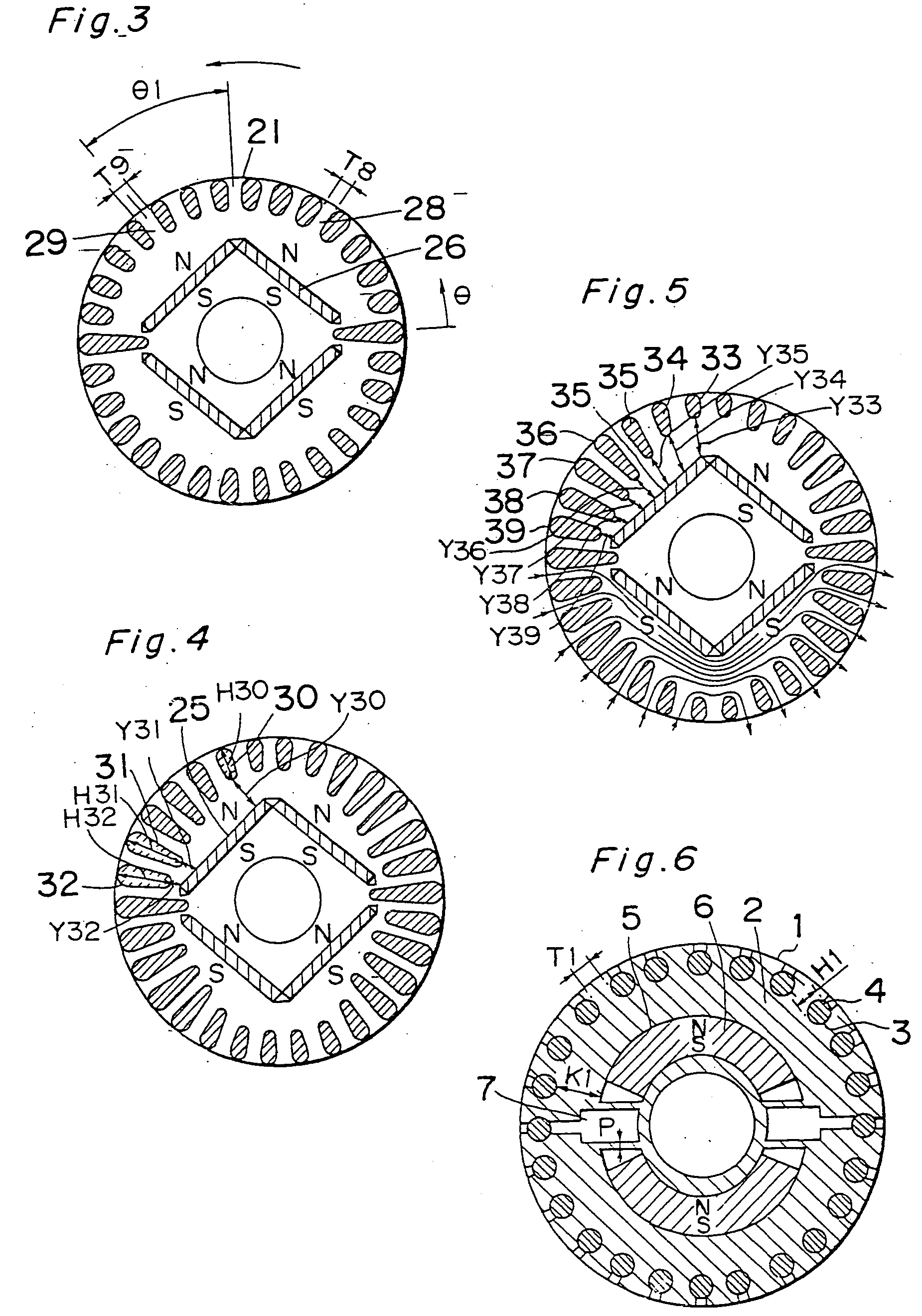
[0131]FIG. 3 illustrates a transverse sectional view of the rotor used in the self-starting permanent magnet synchronous motor according to a second preferred embodiment of the present invention. In FIG. 3, the rotor 21 is shown as rotating in a direction shown by the arrow. During a loaded operation, a composite magnetic flux of the magnetic flux emanating from the stator winding and the magnetic flux emanating from the permanent magnets 26 flows in a larger quantity in a portion 29 between the neighboring slots that are located on a leading side offset θ1 angularly in a direction conforming to the direction of rotation of the rotor, than that flowing in a portion 28 between the neighboring slots that are located on a trailing side from the center of the rotor magnetic poles with respect to the direction of rotation of the rotor. The size of that portion 29, that is, the spacing T8 between the neighboring slots on respective sides of that portion 29 is cho...

third embodiment (fig.4)

THIRD EMBODIMENT (FIG. 4)

[0132]FIG. 4 illustrates a transverse sectional view of the rotor used in the self-starting permanent magnet synchronous motor according to a third preferred embodiment of the present invention. In FIG. 4, one of the slots that is identified by 30 is the slot positioned adjacent the center of the rotor magnetic poles, and the slots 31 and 32 are positioned adjacent one of opposite ends of the rotor magnetic poles. These slots 30, 31 and 32 have different radial lengths H30, H31 and H32, respectively, and the distances Y31 and Y32 between the slot 31 and the magnet retaining hole 25 and between the slot 32 and the magnet retaining hole 25 are chosen to be so smaller than the distance Y30 between the slot 30 and the magnet retaining hole 25 that the magnetic fluxes emanating from the permanent magnets will hardly leak to the outer peripheral surface of the rotor adjacent he ends of the rotor magnetic poles and will, instead, leak to the outer peripheral surfac...


PUM


Abstract

A synchronous motor includes a stator, a rotor and permanent magnets. The rotor includes a rotor iron core rotatable relative to the stator, and a plurality of conductor bars accommodated within corresponding slots in the rotor iron core. The conductor bars have their opposite ends shortcircuited by respective shortcircuit rings to form a starter cage conductor. The rotor also has a plurality of magnet retaining slots defined therein at a location on an inner side of the conductor bars, in which hole permanent magnets are embedded.

Description

[0001] This application is a divisional application of pending U.S. patent application Ser. No. 10 / 792,726, filed on Mar. 5, 2004, which is a divisional of U.S. patent application Ser. No. 10 / 019,286, now U.S. Pat. No. 6,727,627, Jan. 2, 2002, which was the National Stage of International Application No. PCT / JP00 / 04693, filed on Jul. 13, 2000, the disclosures of which are expressly incorporated herein by references in their entireties. The International Application was published under PCT Article 21 (2) in English.TECHNICAL FIELD [0002] The present invention generally relates to a permanent magnet synchronous motor and, more particularly, to the synchronous motor generally used in a motor-driven compressor in a refrigerating system or an air conditioning system or any other industrially utilized electric appliance. BACKGROUND ART [0003] A self-starting permanent magnet synchronous motor operates as an inductor motor at the time of starting thereof owing to a starter squirrel cage co...

Claims


Application Information

Patent Timeline
Patent Type & Authority Applications(United States)
IPC IPC(8): H02K1/22H02K1/27H02K3/04H02K17/26H02K19/14H02K21/46
CPCH02K21/46H02K1/276
Inventor SASAKI, KENJITAMURA, TERUOYOSHIDA, MICHIHIROTAKIMOTO, TORUTANIGUCHI, HIDEYUKIUESAKA, HIROYUKI
Owner PANASONIC CORP
Why Eureka
Try Eureka