MRI apparatus with high-resistance magnet

a magnet and high-resistance technology, applied in the field of rare earth magnets, can solve the problems of oxyfluorine compound being more brittle, affecting the formability of the material, and affecting the use of the material, so as to increase the resistance of a rare earth magnet, increase the residual magnetic flux density, and high density

Inactive Publication Date: 2007-07-12
HITACHI LTD
View PDF2 Cites 4 Cited by
  • Summary
  • Abstract
  • Description
  • Claims
  • Application Information

AI Technical Summary

Benefits of technology

[0006] With regard to the increase of the resistance of a rare-earth magnet, a means thereof is disclosed in JP-A No. 282312 / 2003 as a conventional example. According to the disclosure, when NdF3 is used as a high-resistance material, NdF3 powder and NdFeB alloy powder of 0.2 μm in average grain diameter respectively are mixed in an automatic mortar, but the shape of the fluorine compound is not described, and the shape of the fluorine compound after sintered is a massive form. In contrast, in the present invention, it proposes a high-resistance magnet applied to an MRI apparatus. For example, a fluorine compound to be the high-resistance layer is formed on the surface of magnetic powder as the magnet for MRI by applying surface treatment. The surface treatment is a means of applying a fluorine compound or a fluorine compound containing one or more kinds of alkali metals, alkali-earth metals, or rare-earth elements on the surface of magnetic powder. A gel or sol fluorine compound is smashed in an alcohol solvent, applied on the surface of magnetic powder, and thereafter heated to remove the solvent. The solvent is removed through heat treatment in the temperature range of 200° C. to 400° C. and the fluorine compound is grown through heat treatment in the temperature range of 500° C. to 800° C. For the heat treatment, in addition to externally heating type furnaces such as an electrical resistance heating furnace, an infrared heating furnace, a high-frequency induction heating furnace, and the like, a millimeter wave heating furnace can be used. In a millimeter wave heating furnace, materials are designed so that a high-resistance layer formed on the surface of magnetic powder may be more likely to generate heat than the magnetic powder. That is, by selecting the combination of materials so that the dielectric loss of a high-resistance layer may be larger than that of magnetic powder at a certain temperature, only the high-resistance layer is heated more than the main phase of the magnetic powder and diffusion advances in accordance with the heating of the vicinity of the high-resistance layer. A high-resistance layer can be applied to magnetic powder such as magnet powder, magnetic powder for sintering, anisotropic rare-earth magnet powder, isotropic magnet powder, and soft magnetic powder. The outermost surface layer of such magnetic powder partially reacts with the high-resistance layer; an alkali metal, an alkali-earth metal, or a rare-earth element constituting the high-resistance layer causes substitution reaction with the outermost surface layer; and thus adhesiveness is secured. When a fluorine compound is formed on magnetic powder containing oxygen and heated to a temperature of about 350° C. or higher, the oxygen diffuses. Oxide in magnetic powder combines with a rare-earth element in the magnetic powder in most cases, and such oxygen diffuses into the fluorine compound by the heating and forms an oxyfluorine compound (which is a substance formed by introducing oxygen into a part of a fluorine compound). The oxyfluorine compound is more brittle than a fluorine compound and hence exfoliation from magnetic powder is likely to occur. This is because hardness the oxyfluorine increases and deformation thereof is hardly caused by introducing oxygen into a fluorine compound. Thus cracks tend to appear in the vicinity of the fluorine compound, formability deteriorates, and a high density is hardly obtained. Therefore, it is important to control the oxygen concentration in magnetic powder when a high-resistance layer is formed on the surface of the magnetic powder. Oxide and fluoroxide are likely to be formed at the interface with magnetic powder and formability deteriorates. Instead of the surface treatment, it is possible to make fluorine and a rare-earth element adhere on the surface of the magnetic powder by sputtering from a fluorine compound target in a decompressed atmosphere. Each of a fluorine compound and an oxyfluorine compound has a face centered cubic lattice structure as its crystal structure and the lattice constant is in the range of 0.54 to 0.60 nm. The growth of such a fluorine compound and an oxyfluorine compound, by removing oxygen in magnetic powder, exhibits the effects of the increase of residual magnetic flux density, the increase of magnetic coercive force, the improvement of the squareness of a demagnetization curve, the reduction of the temperature dependency of magnetic properties, the improvement of thermal demagnetizing properties, the improvement of magnetizability, the improvement of anisotropy, the improvement of corrosion resistance, and others.
[0007] As stated above, it is possible to compatibly obtain a high magnetic coercive force, a high residual magnetic flux density, and a high resistance by forming a fluorine compound into a membrane or layer shape at the grain boundaries of alloy of an NdFeB, NdFeCoB, or SmCo type; to avoid the use of an eddy current inhibitor by using such a fluorine compound for a magnetic circuit in an MRI apparatus; and thus is to expand a space to be measured and improve the quality of a measured image.

Problems solved by technology

The magnet of an MRI apparatus is electrically conductive, and that causes the problem of magnetic field gradient-fluctuation caused by eddy current or the variation of the magnetic field of the magnet by heat generation caused by the eddy current.
The oxyfluorine compound is more brittle than a fluorine compound and hence exfoliation from magnetic powder is likely to occur.
Thus cracks tend to appear in the vicinity of the fluorine compound, formability deteriorates, and a high density is hardly obtained.
Oxide and fluoroxide are likely to be formed at the interface with magnetic powder and formability deteriorates.

Method used


Image

  • MRI apparatus with high-resistance magnet
  • MRI apparatus with high-resistance magnet
  • MRI apparatus with high-resistance magnet

Examples


example 1

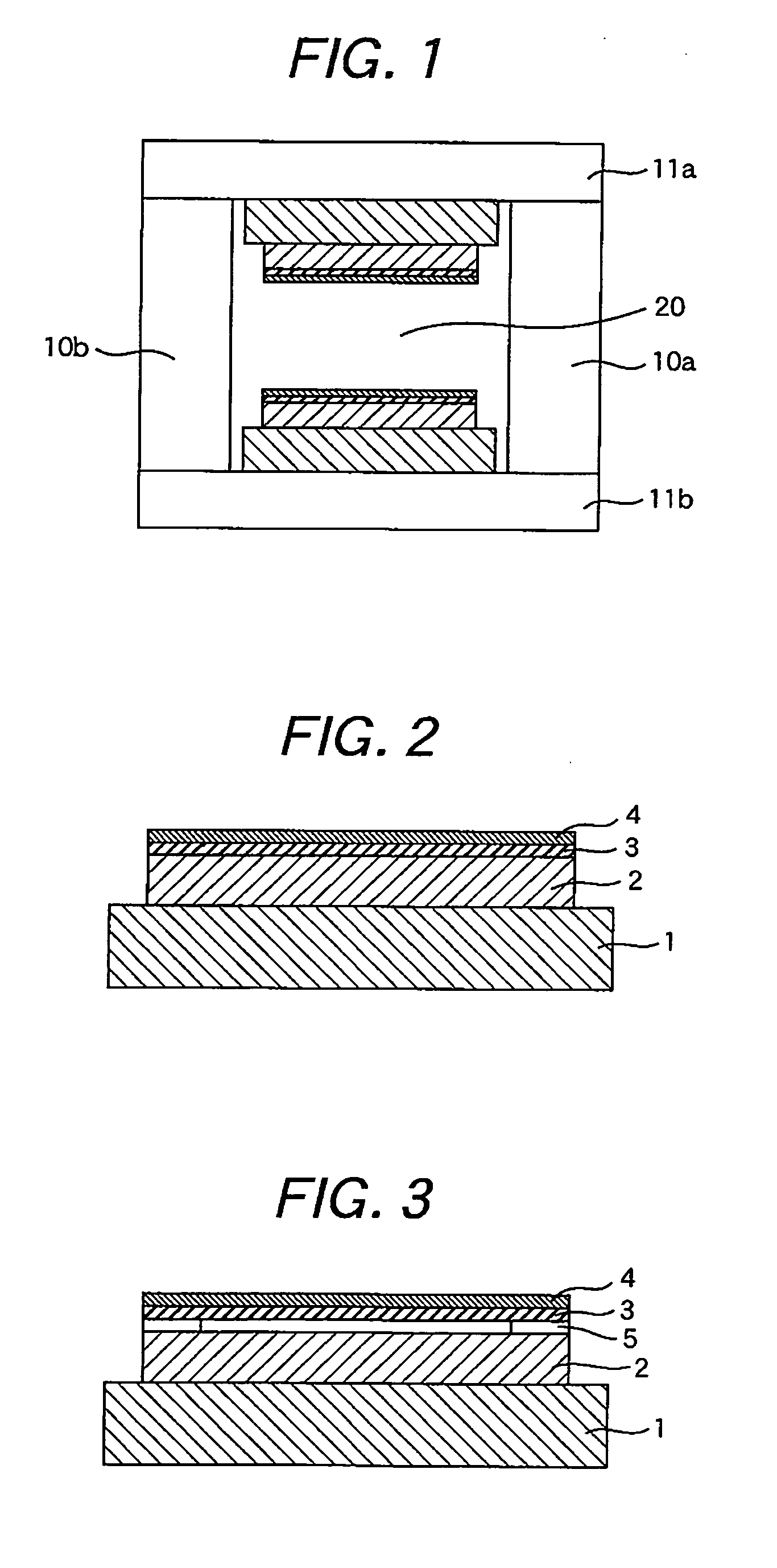
[0015] An example of an apparatus is shown in FIG. 1. In FIG. 1, a pair of permanent magnets 1 supported with upper and lower yokes 11a and 11b, respectively, are disposed at upper and lower positions that interpose a space 20 into which an object to be measured is inserted. The upper and lower yokes 11a and 11b are supported with columns 10a and 10b. A closed magnetic circuit comprised of the upper and lower yokes 11a and 11b and columns 10a and 10b is formed outside the permanent magnets 1. In order to suppress eddy current and reduce hysterisis causing magnetic-circuit loss, a high resistance layer is applied to the grain boundaries in the permanent magnet 1 and soft magnetic material. Here the permanent magnet with the high resistance layer is also referred as a high resistance magnet, and it is used for a part of a sintered magnet. The soft magnetic with the high resistance layer is also referred as a high resistance soft magnetic, it is used for parts of the yokes 11a and 11b....


PUM


Abstract

Eddy current generated around a magnetic circuit in an MRI apparatus is one of the causes of deviation from an ideal magnetic field gradient waveform and causes image distortion, loss of strength, ghost generation, loss of signal, and spectral distortion. An object of the present invention is to suppress the generation of the eddy current. In an MRI apparatus, a ferromagnetic material formed from powder is used in a part of a magnetic circuit: the powder mainly comprising a mother phase containing iron or cobalt and showing ferromagnetism; and a high-resistance layer having a resistance not less than ten times as high as the mother phase and a Vickers hardness lower than that of the mother phase being formed in layers along parts of the surface of the powder on parts or the entire of the surface.

Description

CLAIM OF PRIORITTY [0001] The present application claims priority from Japanese application serial No. 2005-368992, filed on Dec. 22, 2005, the content of which is hereby incorporated by reference into this application. BACKGROUND OF THE INVENTION [0002] The present invention relates to an MRI apparatus to which a high-resistance magnet is applied and a production method of the high-resistance magnet. [0003] In a conventional MRI apparatus in which a ferromagnetic material is used, magnetic field gradient combines with a shield and an electrically conductive structure in a magnet and thereby eddy current is generated as described in JP-A No. 166898 / 2000. Because of the eddy current, the increase and attenuation of magnetic field gradient are observed during and after the application of a trapezoidal current pulse to a gradient coil and the phenomenon leads to image distortion. [0004] In the conventional invention as stated above, a magnetic material that is likely to cause eddy curr...

Claims


Application Information

Patent Timeline
Patent Type & Authority Applications(United States)
IPC IPC(8): G01V3/00
CPCG01R33/3806Y10T428/12014G01R33/3873G01R33/383
Inventor KOMURO, MATAHIROSATSU, YUICHIIMAGAWA, TAKAOISHIKAWA, KATSUMIITABASHI, TAKEYUKI
Owner HITACHI LTD
Why Eureka
Try Eureka