Rare Earth Sintered Magnet, Raw Material Alloy Powder For Rare Earth Sintered Magnet, And Process For Producing Rare Earth Sintered Magnet

a raw material technology, applied in the field of rare earth sintered magnets, can solve the problems of coercive force, drop in mechanical strength, and danger of causing a drop in magnetic properties, and achieve the effects of high residual magnetic flux density, high orientation, and high dispersion state of carbon

Inactive Publication Date: 2007-09-27
TDK CORPARATION
View PDF5 Cites 4 Cited by
  • Summary
  • Abstract
  • Description
  • Claims
  • Application Information

AI Technical Summary

Benefits of technology

[0033] As explained above, according to the present invention a rare earth sintered magnet having a high dispersion state of carbon can be obtained. Therefore, by not increasing the use of a lubricant, which is the cause of carbon being present, orientation is high, so that a rare earth sintered magnet having a high residual magnetic flux density (Br) can be obtained. Based on this assumption, the rare earth sintered magnet according to the present invention can ensure coercive force (HcJ) and mechanical strength.
[0034] In production of the above rare earth sintered magnet according to the present invention, high orientation can be ensured by using a small amount of lubricant, through the use of a raw material alloy powder which is uniformly coated with carbon on its surface (i.e. the lubricant is more uniform). Further, because only a small amount of lubricant needs to be used, the drop in coercive force can be suppressed, and such process is effective in ensuring the mechanical strength. The use of a raw material alloy powder on which the lubricant is more uniformly coated is also effective in improving the strength of the compacted body.

Problems solved by technology

As described above, while a lubricant is effective in improving orientation when compacting in a magnetic field, there is the danger of causing a drop in magnetic properties, especially coercive force, as well as a drop in mechanical strength.

Method used


Image

  • Rare Earth Sintered Magnet, Raw Material Alloy Powder For Rare Earth Sintered Magnet, And Process For Producing Rare Earth Sintered Magnet
  • Rare Earth Sintered Magnet, Raw Material Alloy Powder For Rare Earth Sintered Magnet, And Process For Producing Rare Earth Sintered Magnet
  • Rare Earth Sintered Magnet, Raw Material Alloy Powder For Rare Earth Sintered Magnet, And Process For Producing Rare Earth Sintered Magnet

Examples


example 1

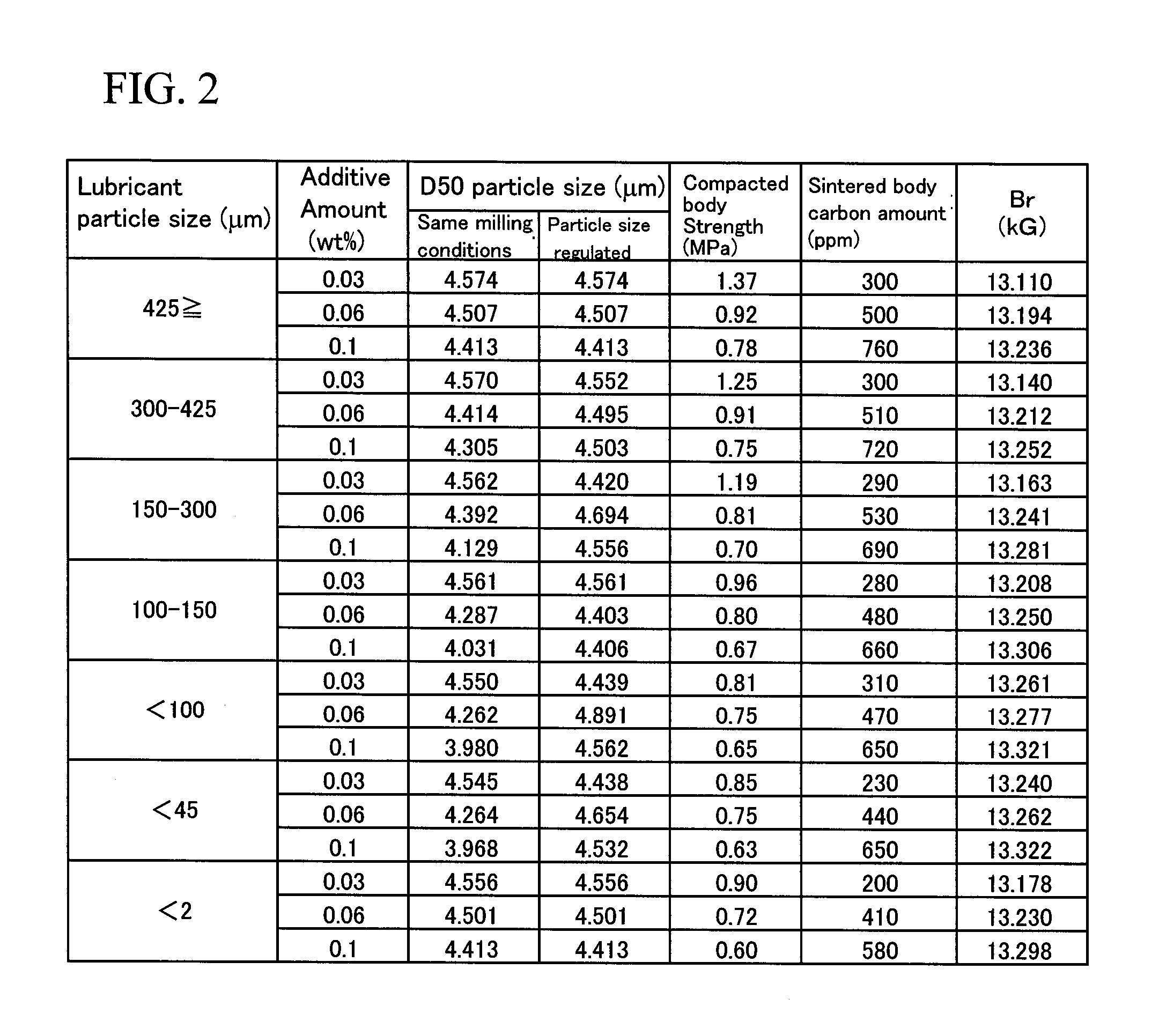
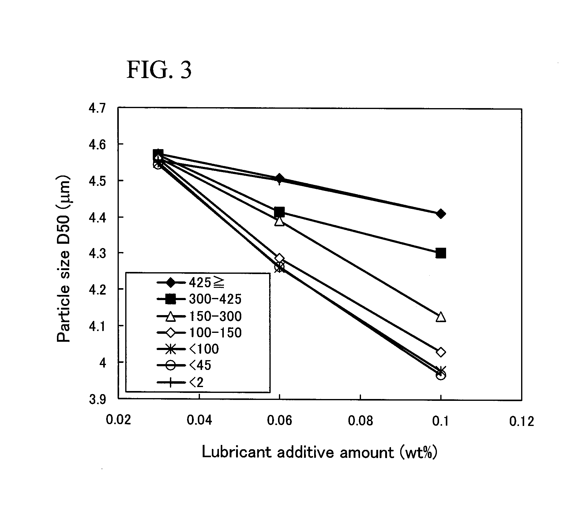
[0102] The influence of particle size of the lubricant added during the milling step was investigated. The results will be illustrated as Example 1.

[0103] The composition of the raw material alloy was 24.5% by weight of Nd, 6.0% by weight of Pr, 1.8% by weight of Dy, 0.5% by weight of Co, 0.2% by weight of Al, 0.07% by weight of Cu, 1.0% by weight of B and the balance being Fe. Metals or alloys which were to become the raw material were blended together so as to form the above-described composition, and the resultant raw material was melted and cast into a raw material alloy thin plate by strip casting. The obtained raw material alloy thin plate underwent hydrogen-pulverizing, and the resultant product was subjected to mechanical pulverizing using a Brown mill, whereby a pulverized powder was obtained.

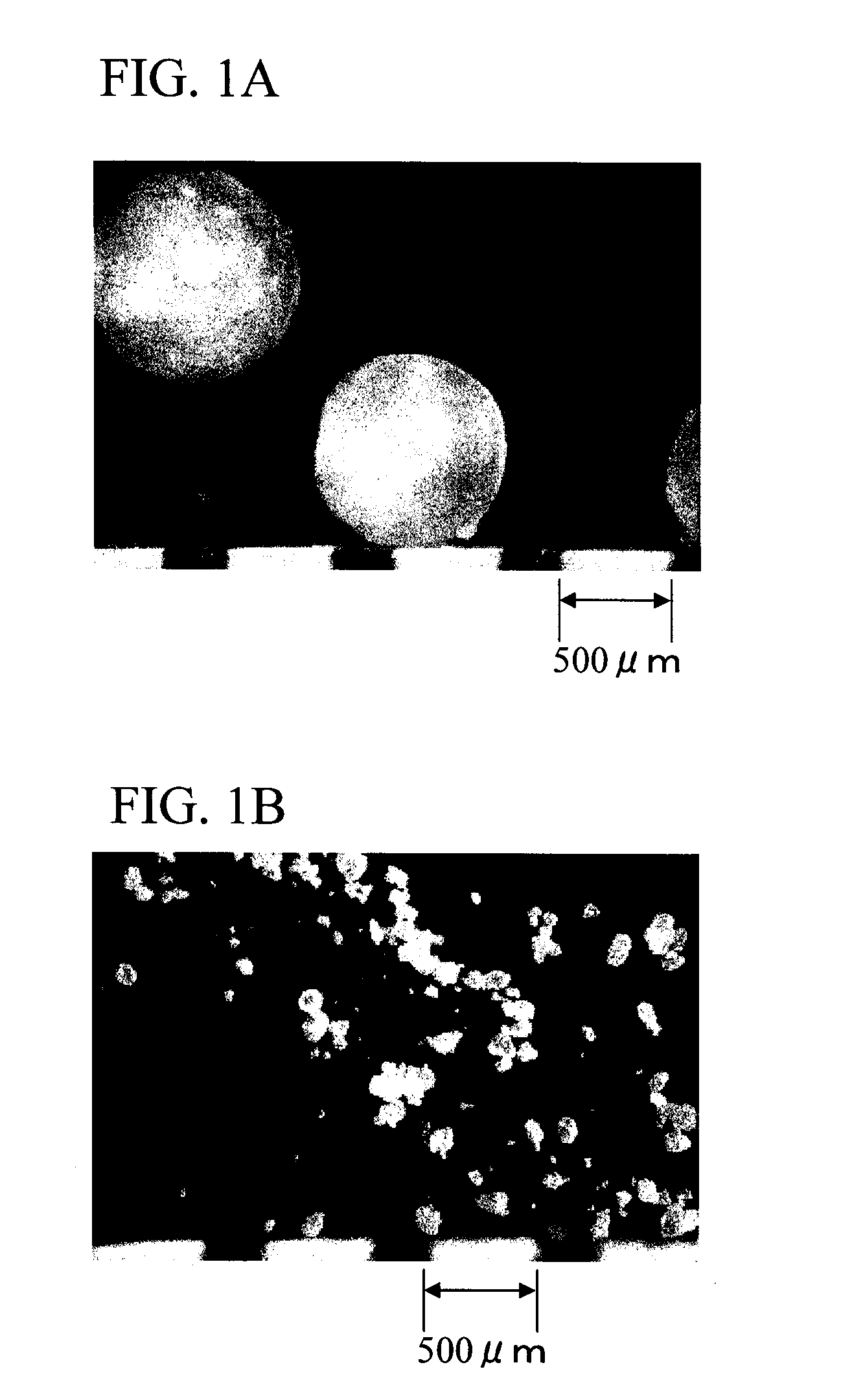
[0104] This pulverized powder was charged with oleic amide as a lubricant. Subsequently, a milled powder was obtained using a jet mill.

[0105] As the lubricant added during the milli...

example 2

[0125] Next, the results of an investigation into the particle size of the raw material alloy (pulverized powder) which was subjected to milling and the particle size of the lubricant is illustrated as Example 2.

[0126] The composition of the raw material alloy was 24.5% by weight of Pr, 6.0% by weight of Dy, 1.8% by weight of Co, 0.5% by weight of Al, 0.2% by weight of Cu, 0.07% by weight of B, and the balance being Fe, and these materials were melted and cast into a raw material alloy thin plate by strip casting. The obtained raw material alloy thin plate underwent hydrogen-pulverizing, and the resultant product was subjected to mechanical pulverizing using a Brown mill, whereby a pulverized powder was obtained. The pulverized powder was formed as a flat sheet, had a thickness of about 100 to 300 μm and a size (length) of about 100 to 1,000 μm. The pulverized powder was classified using a sieve into sizes of 200 μm or more to less than 500 μm and 500 μm or more to less than 800 μm...

example 3

[0143] An R—Fe—B system sintered magnet was produced as described below.

[0144] Metals or alloys which were to become the raw material were blended together so as to form a composition consisting essentially of 24.5% by weight of Nd, 6.0% by weight of Pr, 1.8% by weight of Dy, 0.5% by weight of Co, 0.2% by weight of Al, 0.07% by weight of Cu, 1.0% by weight of B and the balance being Fe. The resultant raw material was melted and cast into a raw material alloy thin plate by strip casting. The obtained raw material alloy thin plate underwent hydrogen-pulverizing, and the resultant product was subjected to mechanical pulverizing using a Brown mill, whereby a pulverized powder was obtained.

[0145] This pulverized powder was charged with oleic amide as a lubricant. Subsequently, a milled powder was obtained using a jet mill.

[0146] As the lubricant charged during the milling, a plurality of kind shaving a differing particle size were prepared. Using commercially available oleic amide (Pr...


PUM

PropertyMeasurementUnit
flexural strengthaaaaaaaaaa
particle sizeaaaaaaaaaa
mean particle sizeaaaaaaaaaa

Abstract

Provided is a rare earth sintered magnet which can attain a high residual magnetic flux density without causing a drop in coercive force or mechanical strength. The above-described problems are resolved by a rare earth sintered magnet which includes a sintered body whose carbon amount as determined by mass spectrometry is between 500 and 1,500 ppm, wherein a cv-value of the carbon amount on a rupture plane thereof is no greater than 200. The production method for this rare earth sintered magnet includes the steps of: preparing a compacted body by compressing in a magnetic field a raw material alloy powder has a carbon amount of no greater than 1,200 ppm as determined by mass spectrometry, and a Cmax/Cmin value of 15 or less wherein Cmax and Cmin respectively represent a maximum value and a minimum value of X-ray intensity of characteristic X-rays of carbon as determined by EPMA (Electron Probe Micro Analyzer); and sintering the compacted body.

Description

TECHNICAL FIELD [0001] The present invention relates to a rare earth sintered magnet as represented by a Nd—Fe—B system, and especially relates to a rare earth sintered magnet whose magnetic properties and mechanical strength are both high. BACKGROUND ART [0002] Rare earth sintered magnets, as represented by a Nd—Fe—B system anisotropic sintered magnet, are widely used as high-performance magnets. To increase the residual magnetic flux density of a rare earth sintered magnet, it is important to improve orientation during compacting in a magnetic field. If orientation becomes higher, the squareness and magnetization rate improve. As a technique for improving orientation of a raw material alloy powder in a magnetic field, various processes to add a lubricant into the raw material alloy powder have been proposed. [0003] For example, Patent Document 1 reports that orientation can be improved by increasing the dispersibility of a lubricant in a raw material alloy powder, by adding the lu...

Claims


Application Information

Patent Timeline
Patent Type & Authority Applications(United States)
IPC IPC(8): H01F1/00B22F1/00
CPCB22F2009/041B22F2998/00B22F2998/10C22C1/0441H01F1/0536H01F1/0577H01F41/0266B22F3/02B22F2202/05B22F9/04B22F1/0059B22F3/10B22F1/10
Inventor ENOKIDO, YASUSHISAKAMOTO, ATSUSHIISHIZAKA, CHIKARAMASUDA, TAKESHIIMURA, MASAAKI
Owner TDK CORPARATION
Why Eureka
Try Eureka