
High gradient disc drive writer

a writer and high gradient technology, applied in the field of magnetic data storage and retrieval systems, can solve the problems of inconsistent writer performance, weakening of fringing magnetic fields, and becoming increasingly difficult to bring the writer closer to the medium, so as to prevent or reduce the fringe erasure field, minimize the distortion of the transition on the disc, and uniform width

Inactive Publication Date: 2005-06-09
SEAGATE TECH LLC
View PDF15 Cites 8 Cited by
  • Summary
  • Abstract
  • Description
  • Claims
  • Application Information

AI Technical Summary

Benefits of technology

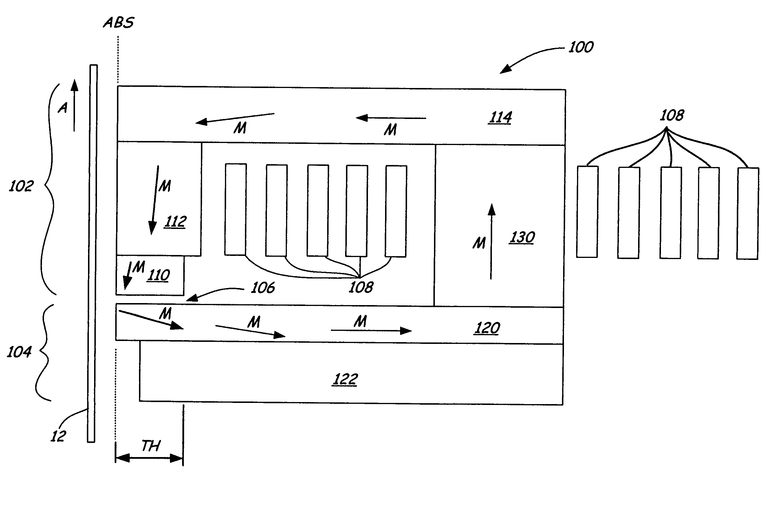
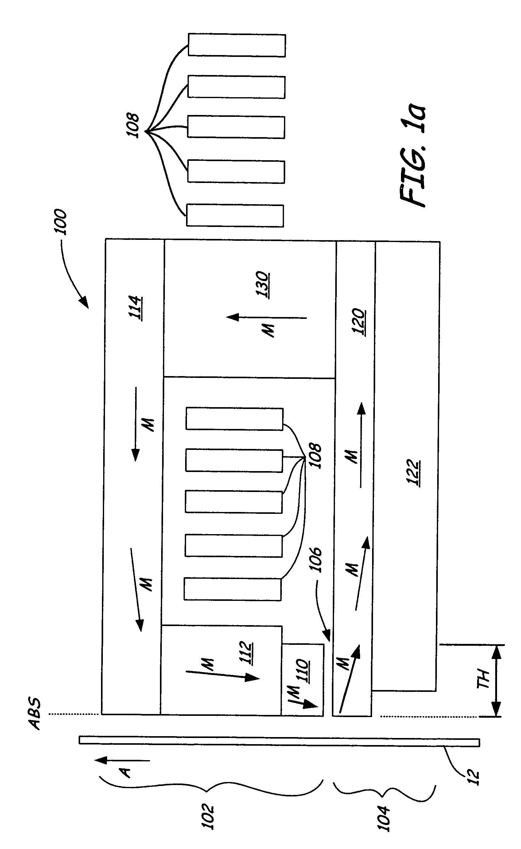
[0007] The present invention is a magnetic writer having an air bearing surface for confronting a surface of a rotating disc. The magnetic writer includes a bottom pole and a top pole. The top pole includes a first top pole portion and a second top pole portion connected by a top pole extension. The top pole extension, which preferably has a uniform width at the air bearing surface, orients a magnetization of the first top pole portion substantially parallel to an air bearing surface of the magnetic writer. This minimizes distortion to transitions on the disc. The bottom pole includes a base pole and a notch pole. The base pole is recessed from the air bearing surface to prevent or reduce fringe erasure fields. The notch pole, which abuts the base pole, has a magnetization oriented perpendicular to the air bearing surface, which maximizes the total field strength in the write gap region, yet avoids distortion to media transitions at the first top pole portion. In one embodiment, the notch pole extends from the air bearing surface beyond the magnetic throat height of the magnetic writer. In another embodiment, the notch pole extends from the air bearing surface to the magnetic throat height of the magnetic writer. Preferably, both the base pole and the notch pole have a flared shape to increase magnetic flux near the air bearing surface.

Problems solved by technology

However, a narrower pole tip causes in a weakening of fringing magnetic fields in the gap layer that write data to the magnetic medium.
This results in inconsistent writer performance.
However, as pole tips continue to decrease in size (and the strength of gap fringing fields correspondingly decreases), it becomes increasingly difficult to bring the writer closer to the medium while maintaining a sufficient fly height above the medium.
While this may improve the gap fringing field strength, the level of improvement is limited by the physics of the materials available.

Method used


Image

  • High gradient disc drive writer
  • High gradient disc drive writer
  • High gradient disc drive writer

Examples


Embodiment Construction

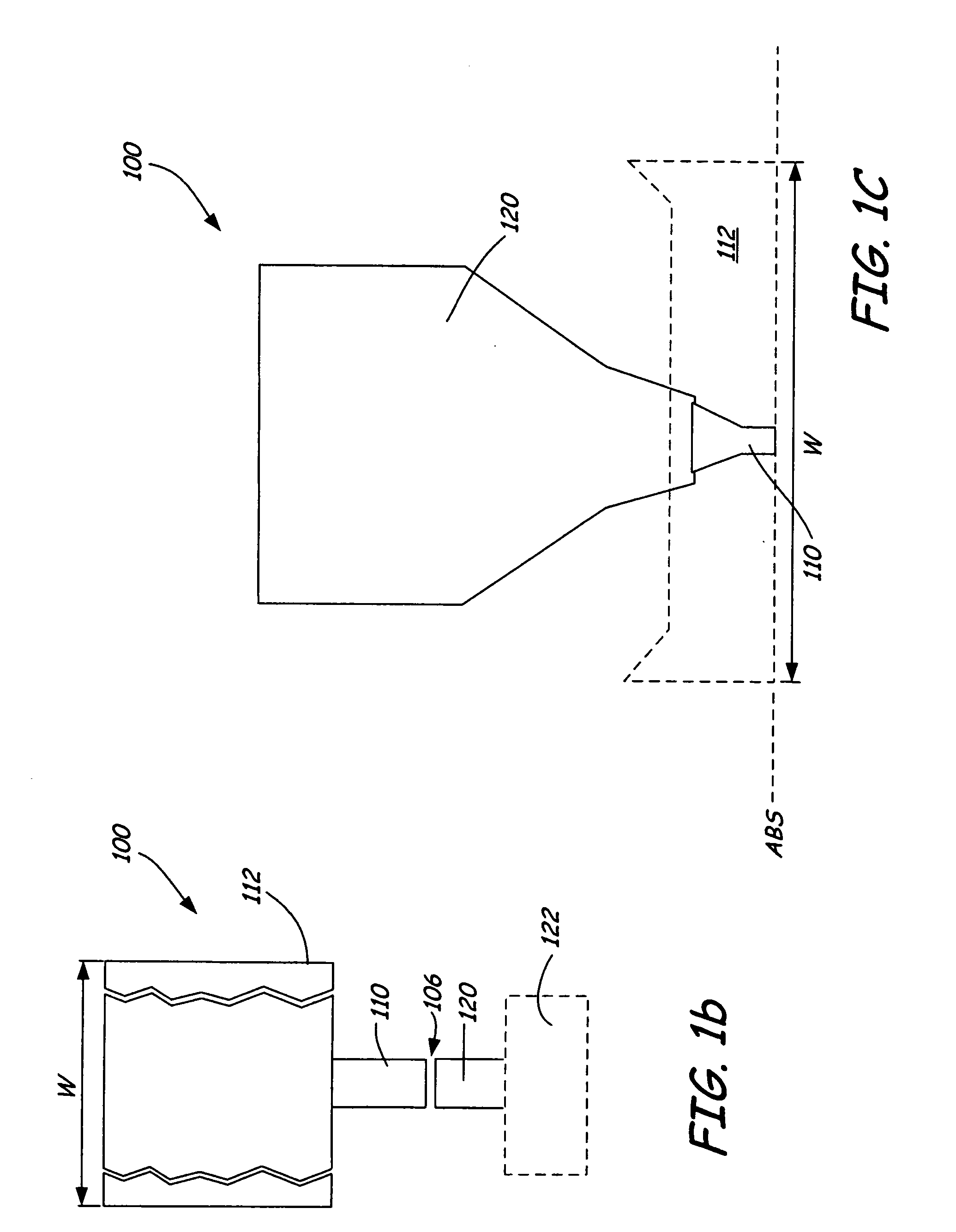
[0014]FIG. 1a is a cross-section view, FIG. 1b is an ABS view, and FIG. 1c is a top view of magnetic writer 100 according to an embodiment of the present invention. Magnetic writer 100 includes top pole 102 and bottom pole 104 separated by gap layer 106. Conductive coils 108 pass through the space between top pole 102 and bottom pole 104. Top pole 102 includes first top pole portion 110, top pole extension 112, and second top pole portion 114. Top pole extension 112 is positioned between first top pole portion 110 and second top pole portion 114. Bottom pole 104 includes notch pole 120 and base pole 122. Base pole 122 is recessed from the ABS and abuts notch pole 120. Top pole 102 and bottom pole 104 are connected to each other distal from the ABS by back gap closer 130. The turns of conductive coils 108 surround back gap closer 130. In FIGS. 1b and 1c, second top pole portion 114 is omitted for clarity, to show the shape of first top pole portion 110, top pole extension 112, and no...


PUM

PropertyMeasurementUnit
magnetizationaaaaaaaaaa
widthaaaaaaaaaa
lengthaaaaaaaaaa

Abstract

A magnetic writer having an air bearing surface for confronting a surface of a rotating disc is disclosed. The magnetic writer includes a bottom pole and a top pole. The top pole includes a first top pole portion and a second top pole portion connected by a top pole extension. The top pole extension, which preferably has a uniform width at the air bearing surface, orients a magnetization of the first top pole portion substantially parallel to an air bearing surface of the magnetic writer. The bottom pole includes a base pole and a notch pole. The base pole is recessed from the air bearing surface to prevent or reduce fringe erasure fields. The notch pole, which abuts the base pole and extends from the air bearing surface to at least a magnetic throat height of the magnetic writer, has a magnetization oriented perpendicular to the air bearing surface.

Description

BACKGROUND OF THE INVENTION [0001] The present invention relates generally to the field of magnetic data storage and retrieval systems. In particular, the present invention relates to a magnetic recording head with a writer portion having a high field gradient and cross-track field uniformity. [0002] In an electronic data storage and retrieval system, a transducing head typically includes a writer for storing magnetically-encoded information on a magnetic disc and a reader for retrieving that magnetically-encoded information from the magnetic disc. The reader typically has two shields and a magnetoresistive (MR) sensor positioned between the shields. Magnetic flux from the surface of the disc causes rotation of the magnetization vector of a sensing layer of the MR sensor, which in turn causes a change in electrical resistivity of the MR sensor. This change in resistivity of the MR sensor can be detected by passing a current through the MR sensor and measuring a voltage across the MR...

Claims


Application Information

Patent Timeline
Patent Type & Authority Applications(United States)
IPC IPC(8): G11B5/127G11B5/147
CPCG11B5/1272
Inventor STAGEBERG, FRANK E.PLUMER, MARTIN L.KONG, VEE S.
Owner SEAGATE TECH LLC
Learn More