

Dielectric ceramic,process for producing the same and laminate ceramic capacitor
a technology of dielectric ceramics and capacitors, applied in the field of dielectric ceramics, can solve the problems of insufficient presence of form at ba sites and mg in solid solution at ti sites, and achieve the effects of reducing the thickness of the dielectric ceramic layer, improving humidity resistance, and improving high-temperature reliability
- Summary
- Abstract
- Description
- Claims
- Application Information
AI Technical Summary
Benefits of technology
Problems solved by technology
Method used
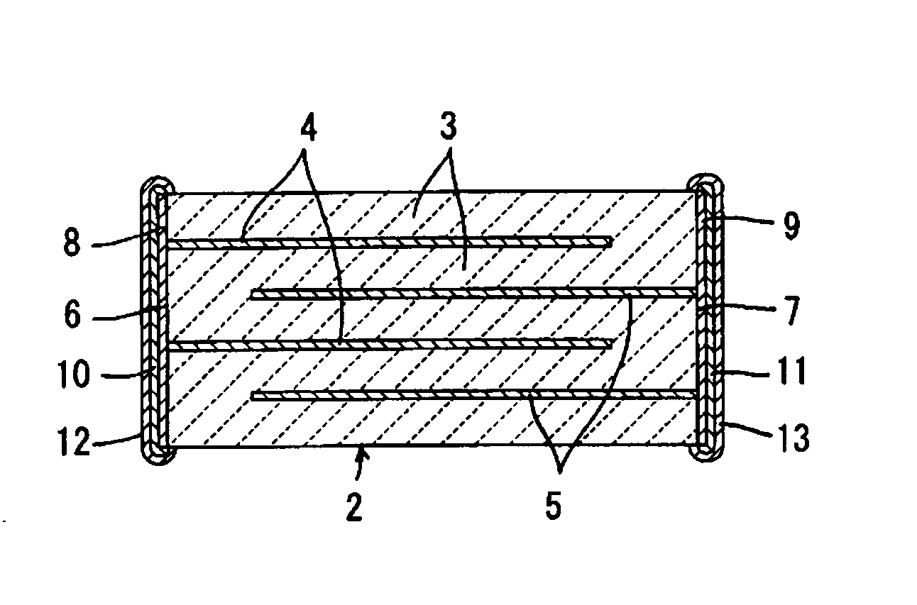
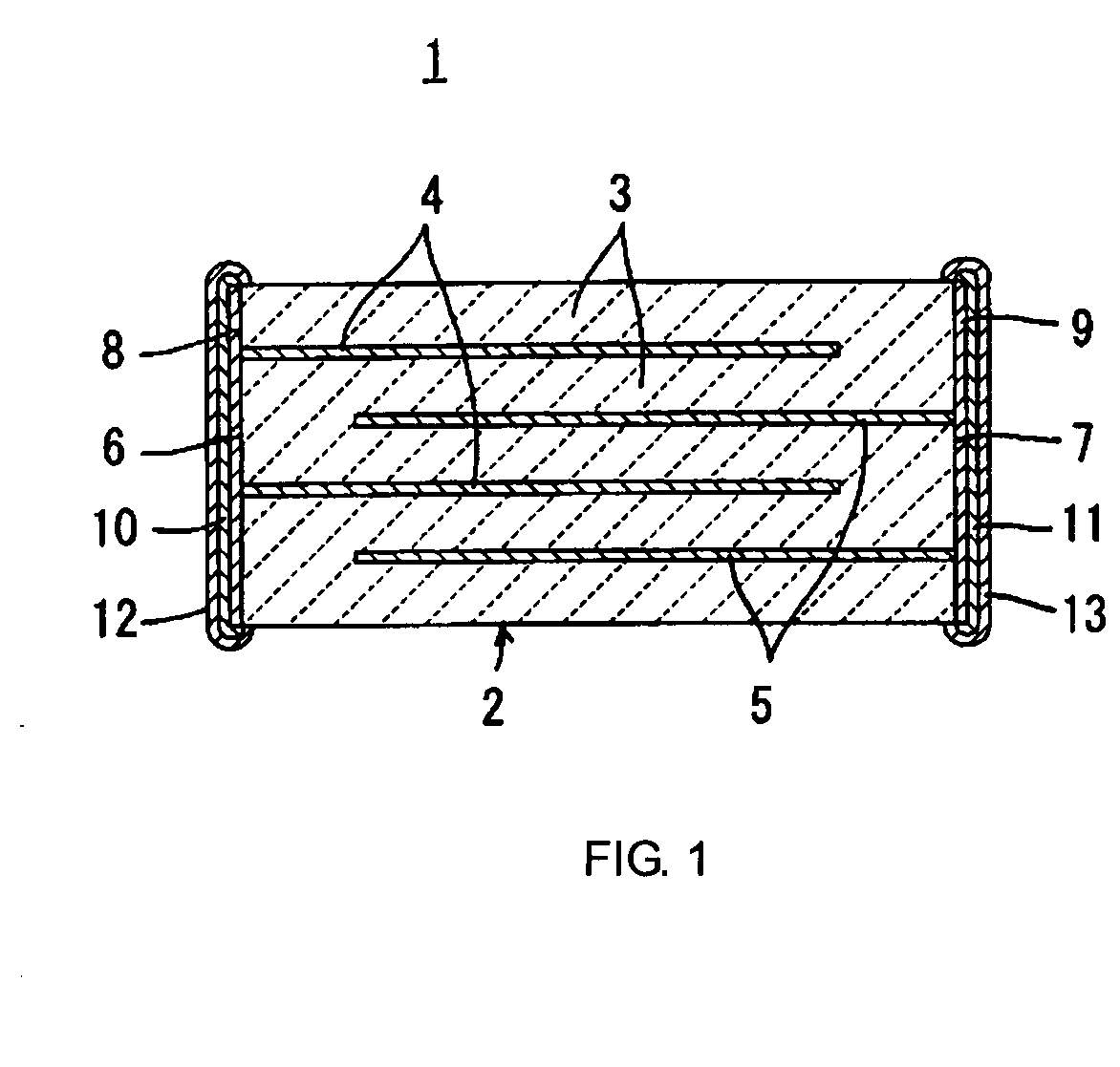
Image

Examples
experimental example 1
[0069] As stating materials for a dielectric ceramic, powdered BaCO3, CaCO3, SrCO3, TiO2, ZrO2, HfO2, Gd2O3, MgCO3, MnO, NiO, and SiO2, each having a purity of 99.8% or more, were prepared.
[0070] Next, in order to obtain a first reaction product represented by (Ba1-h-i-mCahSriGdm) k (Ti1-y-j-nZryHfjMgn)O3, specified materials among the above starting materials were mixed together in accordance with the composition in the column of “First Reaction Product” shown in Tables 1 and 2 and were then calcined in the air, followed by pulverization.
[0071] In addition, in order to obtain a second reaction product containing Ma (at least one of Ba, Sr, and Ca), Mb (at least one of Mn and Ni), and Mc (Si or both Si and Ti), specified materials among the above starting materials were mixed together in accordance with the composition in the column of “Second Reaction Product” shown in Tables 1 and 2 and were calcined in the air, followed by pulverization.
[0072] In the column of “Second Reaction...
experimental example 2
[0102] As stating materials of the dielectric ceramic, powdered BaCO3, TiO2, ZrO2, HfO2, Gd2O3, MgCO3, CaCO3, SrCO3, MnO, NiO, and SiO2, each having a purity of 99.8% or more, were prepared, and in addition to powdered R2O3 in which R was an element shown in the column of “R2O3” in Table 5, powdered Al2O3 was also prepared.
[0103] Next, in order to obtain a first reaction product represented by (Ba0.97Ca0.01Gd0.02)0.999(Ti0.95Zr0.02Hf0.01Mg0.02)O3, predetermined amounts of BaCO3, TiO2, ZrO2, HfO2, Gd2O3, MgCO3, and CaCO3 among the above mentioned starting materials were mixed together and were then calcined in the air, followed by pulverization.
[0104] In addition, in order to obtain a second reaction product containing Ma, Mb, and Mc, BaCO3, SrCO3, MnO, NiO, SiO2, and TiO2 among the above starting materials were mixed together so that molar ratios of Ba:Sr:Mn:Ni:Si:Ti with respect to 100 moles of the first reaction product were set to 0.6:0.1:0.3:0.1:0.8:0.2, and were then calcined...
experimental example 3
[0109] As stating materials of a dielectric ceramic, powdered BaCO3, SrCO3, TiO2, ZrO2, Gd2O3, MgCO3, MnO, and SiO2, each having a purity of 99.8% or more, were prepared.
[0110] Next, by the use of the stating materials mentioned above, the powdered dielectric ceramic starting materials such as samples 3-1 to 3-5 were formed. In all the samples 3-1 to 3-5, the molar ratios of Ba:Sr:Gd:Ti:Zr:Mg:Mn:Si were set to 96.4:2:2:96:2:2:0.2:1.5.
[0111] (1) Sample 3-1
[0112] In order to obtain a first reaction product represented by (Ba0.96Sr0.02Gd0.02) (Ti0.96Zr0.02Mg0.02)O3, predetermined amounts of BaCO3, SrCO3, Gd2O3, TiO2, ZrO2, and MgCO3 among the above starting materials were mixed together and were then calcined in the air, followed by pulverization.
[0113] In addition, in order to obtain a second reaction product containing Ma, Mb, and Mc, BaCO3, MnO, and SiO2 among the above starting materials were mixed together so that 0.4 moles of Ba, 0.2 moles of Mn, and 1.5 moles of Si were conta...
PUM
| Property | Measurement | Unit |
|---|---|---|
| Grain size | aaaaa | aaaaa |
| Grain size | aaaaa | aaaaa |
| Grain size | aaaaa | aaaaa |
Abstract
Description
Claims
Application Information