Method and circuit for multiplying signals with a transistor having more than one independent gate structure

a gate structure and transistor technology, applied in the field of mixers, can solve the problems of relatively small and easy implementation of mixer circuits

Inactive Publication Date: 2005-06-09
NORTH STAR INNOVATIONS
View PDF11 Cites 248 Cited by
  • Summary
  • Abstract
  • Description
  • Claims
  • Application Information

AI Technical Summary

Problems solved by technology

Designers of high frequency mixer circuits have been faced with the problem of providing a relatively small and easy to implement mixer circuit that provides highly linear operation at low power supply voltages (e. g.

Method used


Image

  • Method and circuit for multiplying signals with a transistor having more than one independent gate structure
  • Method and circuit for multiplying signals with a transistor having more than one independent gate structure
  • Method and circuit for multiplying signals with a transistor having more than one independent gate structure

Examples


Embodiment Construction

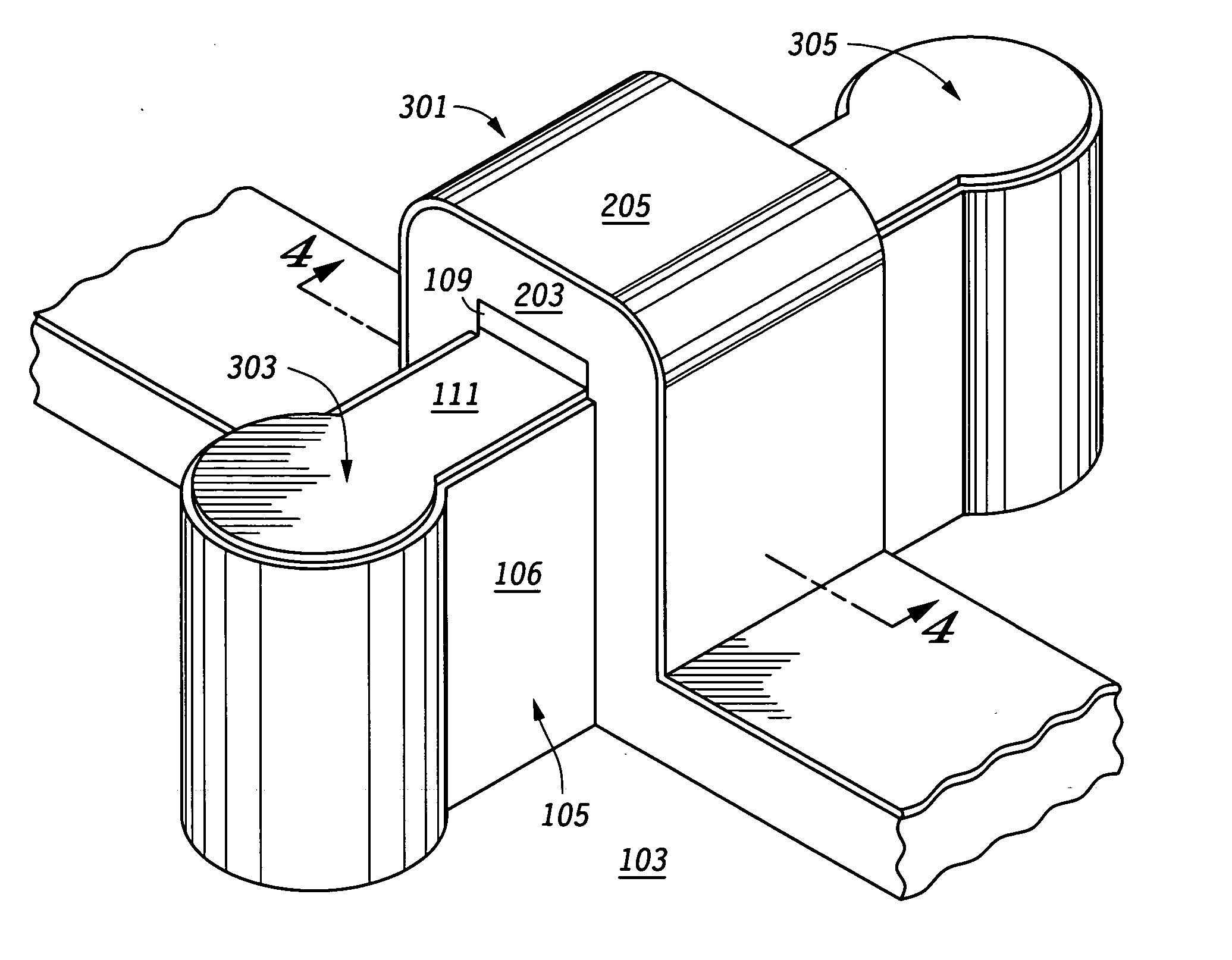
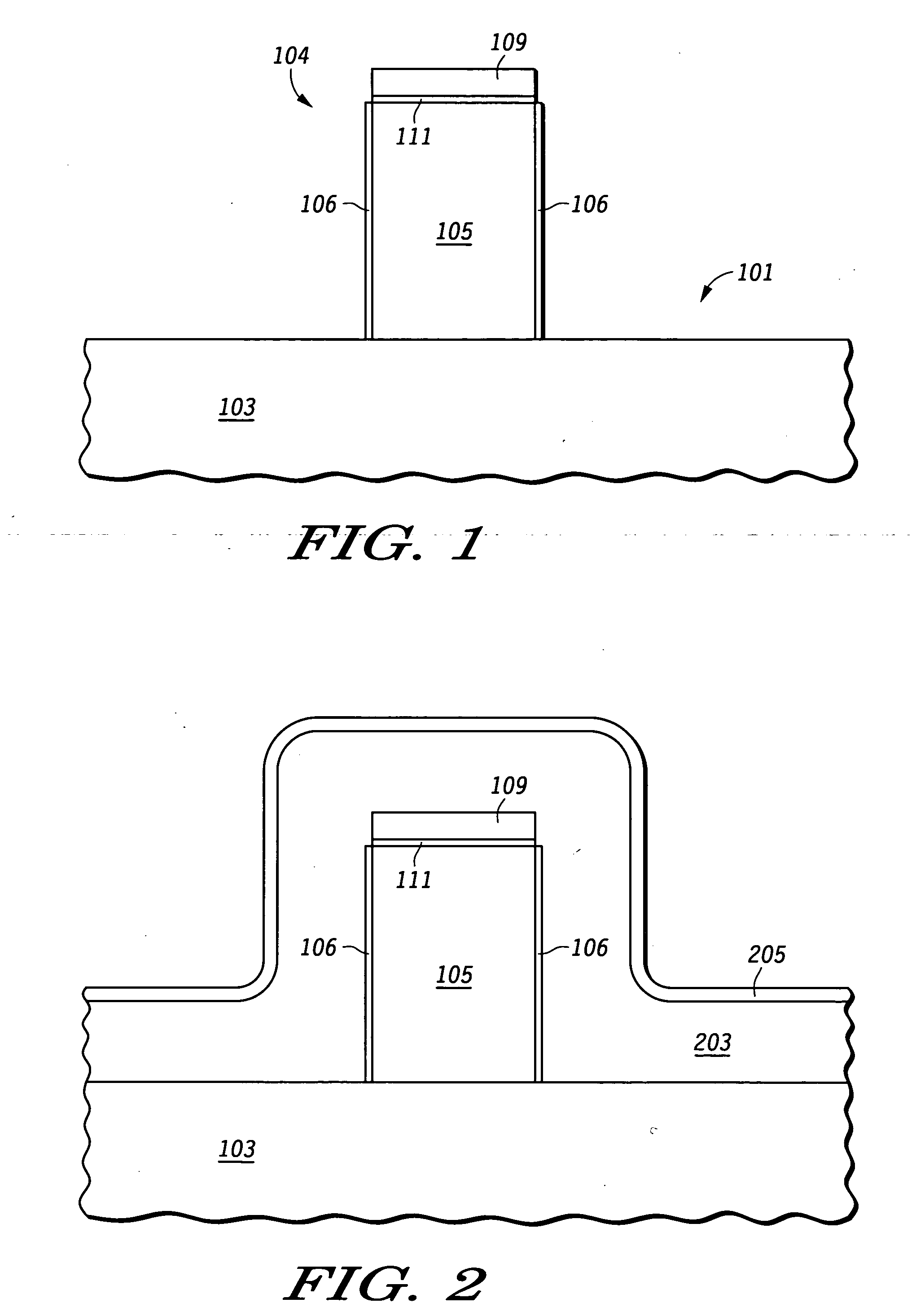
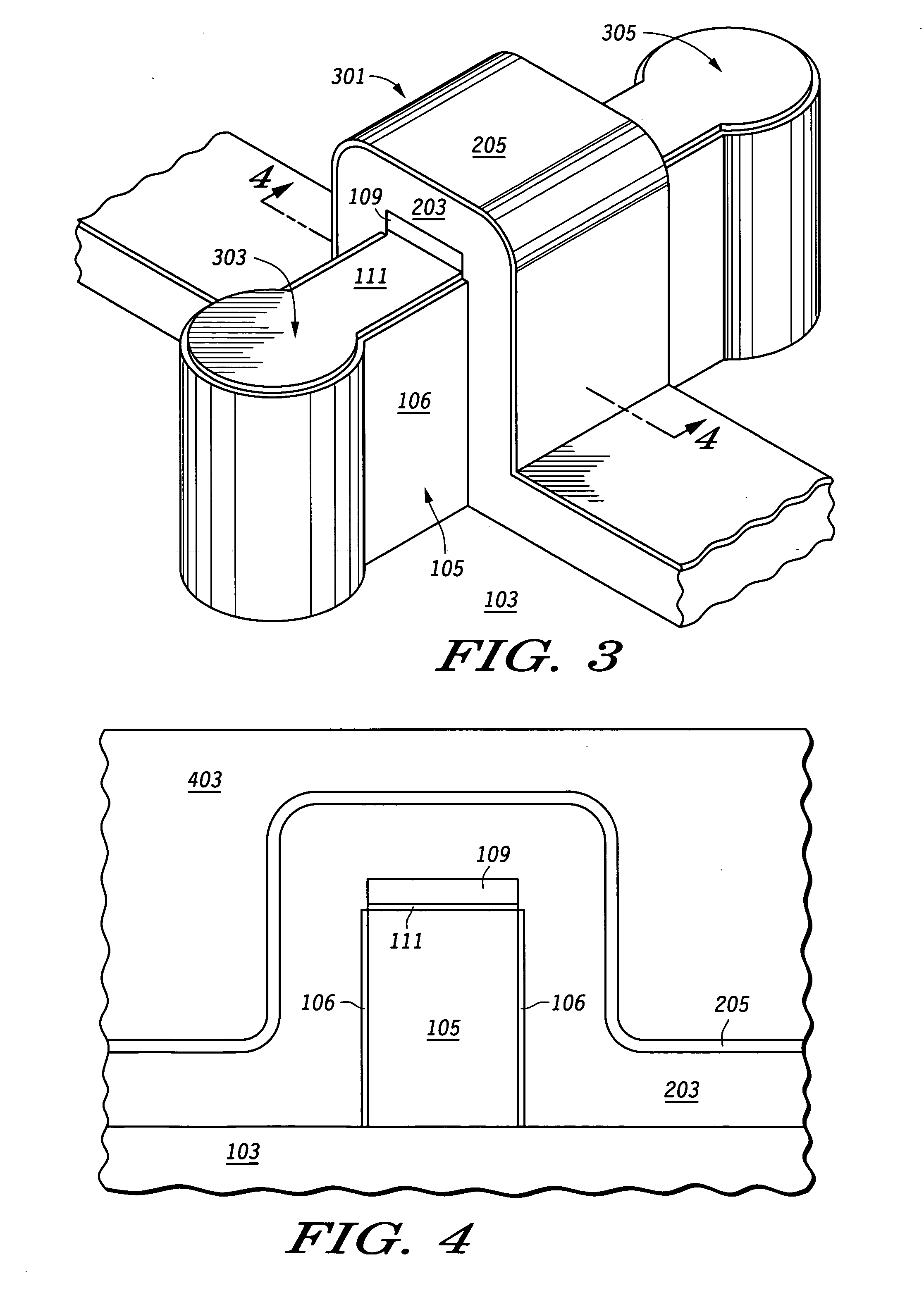
[0031] Generally, the present invention provides a multiplier circuit. The multiplier circuit includes a semiconductor “fin” formed on a substrate. The fin has first and second sidewalls. A layer of gate material is formed over the substrate and the fin, the gate material including a first portion adjacent to the first sidewall of the fin and a second portion adjacent to the second sidewall of the fin. The layer of gate material is removed from over the semiconductor fin to leave a first gate along the first sidewall and a second gate along the second sidewall, where the first and second gates have a predetermined height and are electrically isolated from each other. The first and second gates function as input terminals for the multiplier circuit and a first input signal is applied to the first gate and a second input signal to be multiplied with the first input signal is applied to the second gate. In another embodiment, the multiplier circuit functions as a mixer circuit.

[0032] ...


PUM


Abstract

A double gate semiconductor device (2006) is used beneficially as a multiplier (2000). The double gate semiconductor device (2006) has a lateral fin (105) as the channel region with the gates formed opposite each other on both sides of the fin. The lateral positioning of the fin provides symmetry between the two gates. To increase drive current, multiple transistors are easily connected in parallel by having a continuous fin structure (2106) with alternating source/drain terminals (2120, 2122, 2124, 2126) in which the sources are connected together and the drains are connected together. Gates (2116, 2110) are positioned between each pair of adjacent source/drain terminals and electrically connected together. The multiplier (2000) may also be used as a mixer and further as a phase detector.

Description

RELATED APPLICATIONS [0001] This application is related to the application entitled “Transistor With Independent Gate Structure”, by Mathew et al., having application Ser. No. 10 / 443,375, filed on May 22, 2003, and assigned to the assignee hereof. [0002] This application is related to the application entitled “Memory With Charge Storage Locations”, by Mathew et al., having application Ser. No. 10 / 443,908, filed on May 22, 2003, and assigned to the assignee hereof.FIELD OF THE INVENTION [0003] This invention relates generally to mixers and more specifically to a method for mixing signals with a transistor having more than one independent gate structure. BACKGROUND OF THE INVENTION [0004] A mixer circuit is a type of multiplier circuit that provides frequency translation for two or more signals. For example, in a radio receiver, a mixer circuit is used to translate an RF (radio frequency) signal to an IF (intermediate frequency) signal. In an integrated circuit mixer, the signals to b...

Claims


Application Information

Patent Timeline
Patent Type & Authority Applications(United States)
IPC IPC(8): H01L21/336H01L21/8234H01L21/84H01L29/423H01L29/786
CPCH01L21/823437H01L21/84H01L29/785H01L29/66818H01L29/42384
Inventor DU, YANGMATHEW, LEO
Owner NORTH STAR INNOVATIONS
Why Eureka
Try Eureka