Array transducer for 3D tilting probes

a technology of array transducer and tilting probe, which is applied in the field of construction and manufacturing of ultrasonic 3d probes, can solve the problems of reducing the quality of system, affecting the operation of the system, and affecting the quality of the system,

Active Publication Date: 2005-06-09
VERMON
View PDF7 Cites 45 Cited by
  • Summary
  • Abstract
  • Description
  • Claims
  • Application Information

AI Technical Summary

Benefits of technology

[0053] It is still another object of the invention to provide a method and apparatus for producing 3D images that includes a curved array transducer adapted to be pivoted or rotated around an axis and of shape conformal to the internal surface of the probe shell, the transducer further including a piezoelectric member having a surface of progressive curvature in elevation such as to compensate for the focalization variation effect of the lens when shifti

Problems solved by technology

Finally, 2D mechanical moving transducer devices are much less commonly commercially available because of the intricate moving mechanism employed and the associated effective lack of reliability.
However, solid state materials that perfectly match the acoustic impedance of the human body and the coupling liquid do not exist in practice so that artifacts are usually encountered on the resultant images and these contribute to degrade the quality of system.
However, the general problem is even more complicated with systems employing curved linear array transducers.
Thus, a principle is stated with some limitations, but no detail is provided on how the transducer is acoustically coupled to the probe shell.
Unfortunately, in practice, the coupling fluid volume located between the transducer and the probe front shell is responsible for acoustic artifacts which are visible in the proximal zone of the resultant images.
However, this method of reflecting echo suppression results in a complicated probe construction and the acoustic path for every single element of array is inherently modified, from the center to the outermost elements of the array, thereby creating an undesired apodisation function.
Another shortcoming of this approach concerns the liquid bath surrounding the transducer; strong liquid turbulen

Method used


Image

  • Array transducer for 3D tilting probes
  • Array transducer for 3D tilting probes
  • Array transducer for 3D tilting probes

Examples


Embodiment Construction

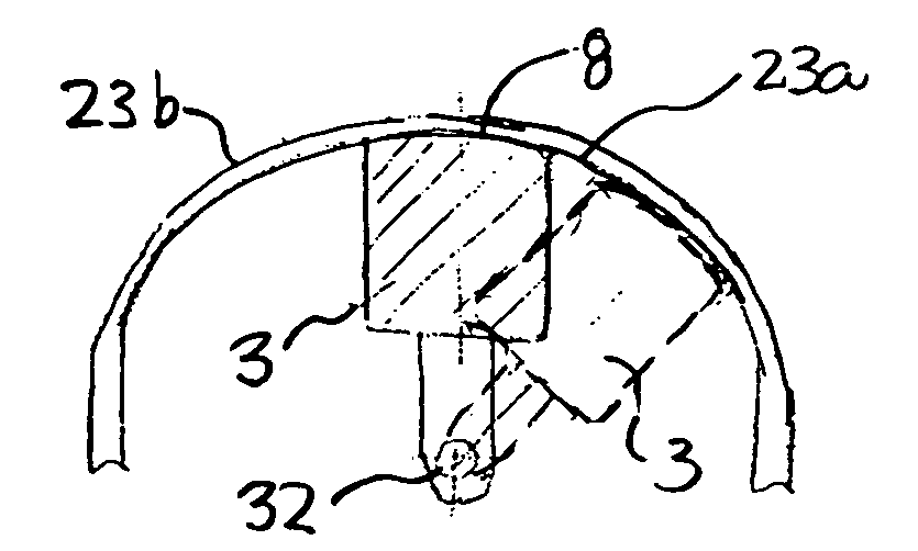
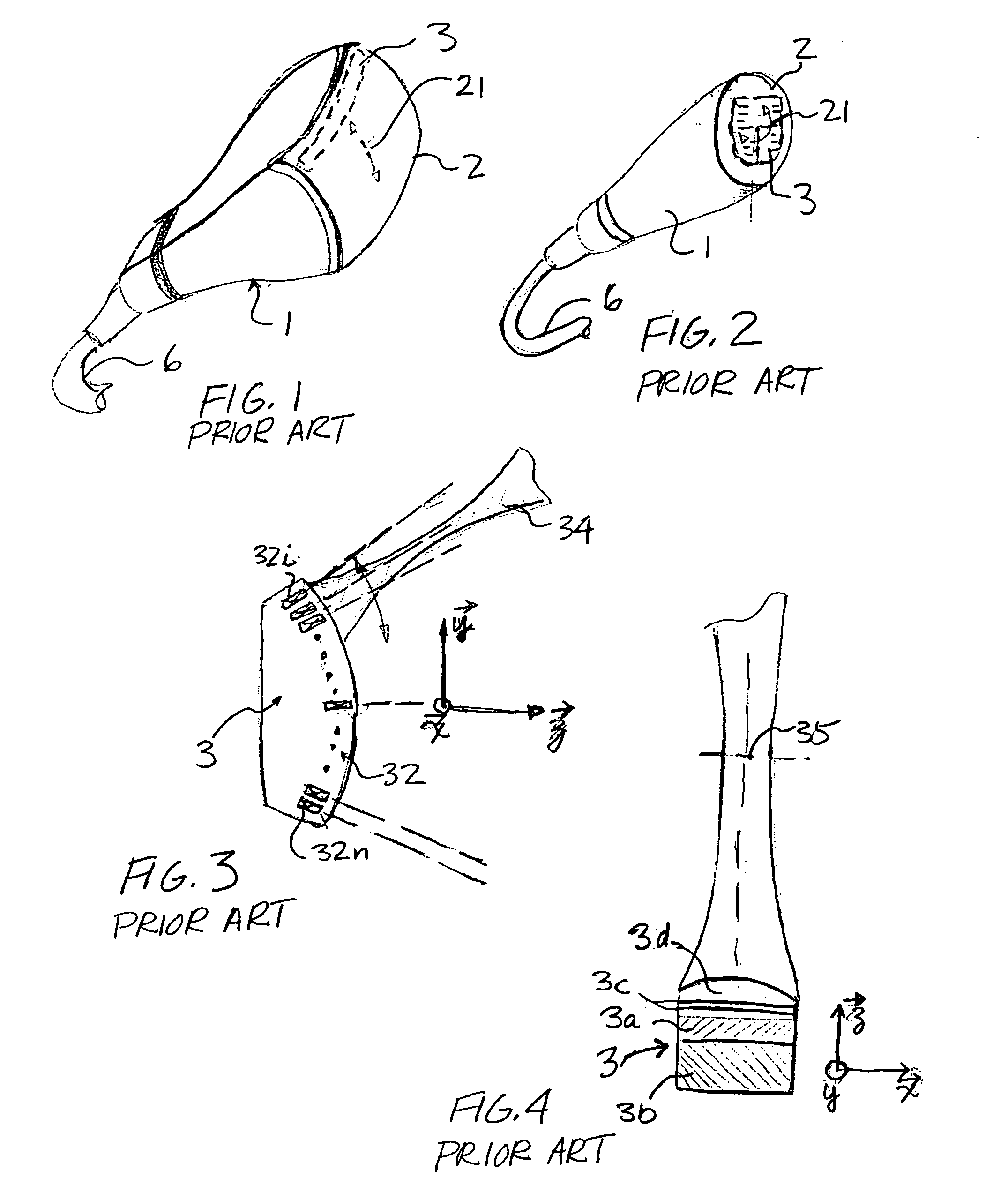
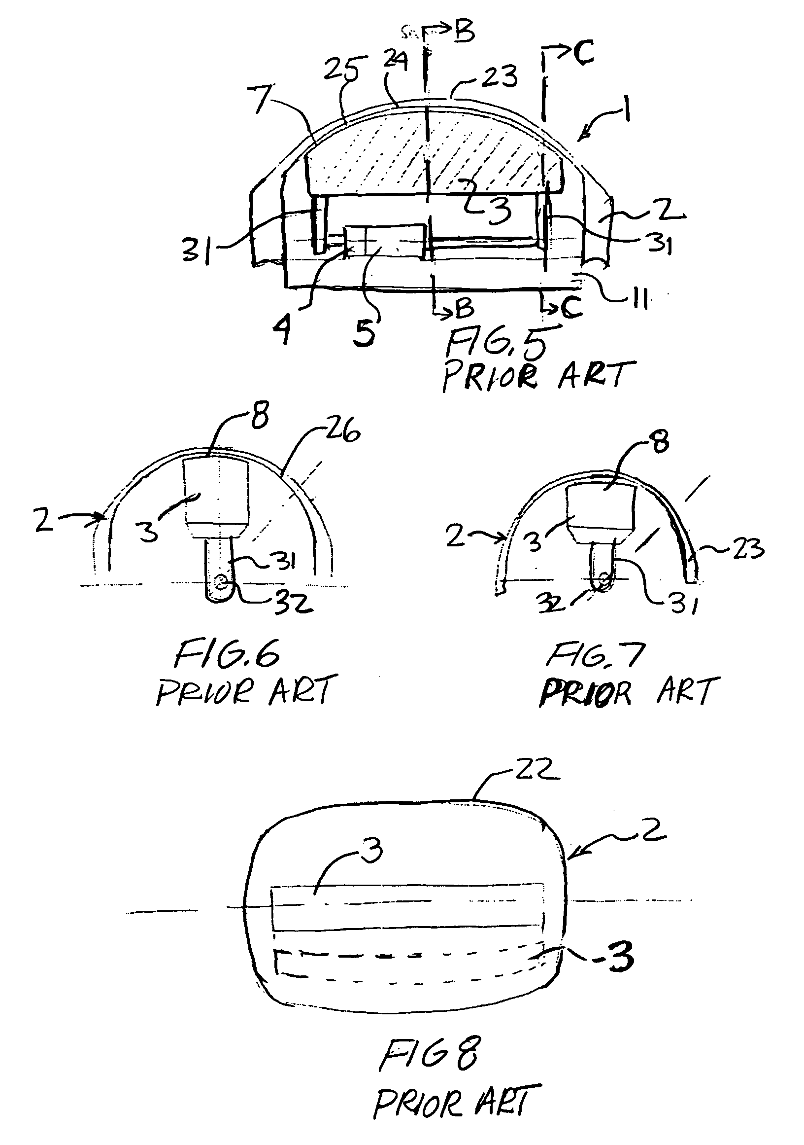
[0074] As illustrated by the prior art discussed above, three dimensional hybrid probes for medical diagnostic use have been developed and described. However, all prior art devices are affected with similar shortcomings that limit their widespread commercial use. FIG. 1 illustrates an ultrasonic hybrid probe 1 equipped with a swinging / tilting curved array transducer 3 disposed underneath the front shell 2 of the probe 1. The transducer 3 is conventionally caused to rotate or swing in a coupling liquid bath so that acoustic energy is emitted from, and received through, the front shell 2. Transducer 3 conventionally comprises a plurality of elementary vibrators uniformly disposed along the azimuth axis thereof to provide electronic scanning of images. Probe 1 also comprises an internal mechanism (not shown) that carries transducer 3, and a motorization means (not shown), i.e., an electric motor drive, for providing swinging of the transducer. The transducer 3 is secured to the interna...


PUM


Abstract

An ultrasonic apparatus is provided for producing three dimensional images using at least one moving curved array transducer for scanning a volume of a region of interest to be imaged. The apparatus includes an acoustic front shell having complex shape and an ultrasonic transducer adapted for swinging movement underneath the front shell and having a front surface of a shape conforming to the complex shape of the front shell. A motor provides the swinging movement of the ultrasonic array transducer underneath the front shell so as to scan a volume of the region of interest. The shell and a transducer carrier may be of an ovoid shape. The transducer may include lips at superior edges thereof which contain a coupling grease. Multiple transducers for different applications may be employed.

Description

FIELD OF THE INVENTION [0001] This invention relates to the construction and manufacturing of an ultrasonic 3D probe which incorporates an array transducer for mechanically scanning an angular sector. The mechanical movement of the transducer is preferably obtained by tilting or swinging the transducer around its azimuthal longitudinal axis, and such probes are typically dedicated to use in medical diagnosis or in the non-destructive evaluation of materials. BACKGROUND AND RELATED ART [0002] The use of volumetric image rendering techniques in ultrasonic scanning is becoming one of the most exciting modalities in modern medical diagnostics. Currently, a number of sophisticated systems are capable of 3D imaging and surface representation that provide patients and users with both figurative images and comprehensive data information. The diagnostic results can be displayed either as surface images (3D) or as 2D scanning representations (i.e., a conventional representation) in order to g...

Claims


Application Information

Patent Timeline
IPC IPC(8): A61B8/00G10K11/35
CPCA61B8/4281G10K11/355A61B8/483A61B8/4461
Inventor FLESCH, AIME
Owner VERMON
Why Eureka
Try Eureka