Method of testing friction components for automatic transmissions

Inactive Publication Date: 2005-06-16
LINK ENG
View PDF10 Cites 15 Cited by
  • Summary
  • Abstract
  • Description
  • Claims
  • Application Information

AI Technical Summary

Benefits of technology

[0012] According to one aspect of the present invention, a method of testing a friction component for an automatic transmission is provided that more accurately simulates friction component performance. The method comprises installing a friction component in a test stand having a drive shaft and a grounding anchor with a first part of the friction component attached to the drive shaft and a second part of the friction component attached to the grounding anchor. The drive shaft of the test stand is rotated with a motor drive until the drive shaft including the first part of the friction component rotates at a target sliding speed Vtarget and continues rotation at that speed. An actuation force is ap

Problems solved by technology

If friction components are not properly designed or matched to an automatic transmission, shifting may be rough, jerky, or inefficient.
In addition, the reliability and durability of friction components may be reduced.
However, engagement conditions on SAE#2 test stands are inconsistent with the shifting kinematics of many automatic transmission systems.
However, in a conventional inertia-absorption test, the slip speed starts decreasing as soon as the engagement torque starts rising.
Due to this inconsistent slip speed profile, conventional test methods used on friction component test sta

Method used


Image

  • Method of testing friction components for automatic transmissions
  • Method of testing friction components for automatic transmissions
  • Method of testing friction components for automatic transmissions

Examples


Example

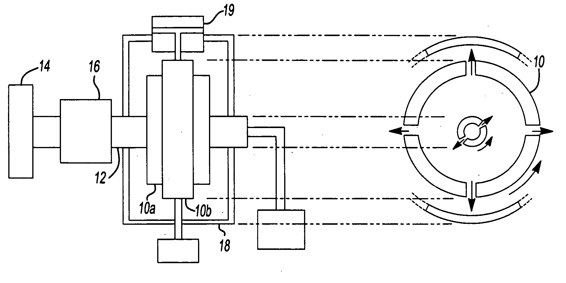
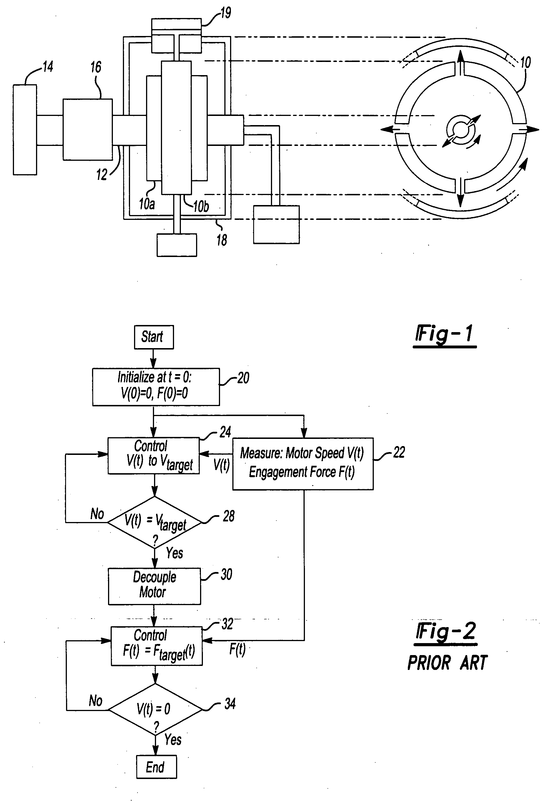
[0028] Referring now to FIG. 4, a flow diagram illustrates implementation of an improved control procedure for an SAE#2 friction component test stand according to one embodiment of the present invention. At a block 40, the test control system initializes control variables V(t) and F(t) at t=0, such that V(0)=0, and F(0)=0. Drive shaft speed V(t) and engagement force F(t) are measured at a block 42. Other variables also measured during the test include friction component engagement torque T(t). To prepare for friction component engagement, the drive motor 16 raises the drive shaft 12 speed to a prescribed value Vtarget at a block 44 and a decision block 46. Once V(t) reaches its target value of Vtarget as shown in the decision block 46, the test control system begins controlling engagement force F(t) as shown in an action block 48. Values of F(t) are equated to Ftarget(t) using either an open-loop control or a closed-loop control with measurements of F(t) as a feedback signal. The te...


PUM


Abstract

A method of testing a friction component for a transmission that has first and second parts. The first part of the friction component is attached to a drive shaft and the second part is attached to a grounding element. The first part of the friction component is rotated until the drive shaft and the first part of the friction component rotate at a target sliding speed Vtarget. An actuation force is applied to the friction component at a time t0. Operation of the motor drive is continued to maintain the speed of rotation of the drive shaft at Vtarget until a predetermined level of engagement torque Tth is obtained. The motor torque is then reduced to a predetermined level Tm. The sliding speed of the drive shaft is then decreased and the test is terminated when the sliding speed falls to zero.

Description

BACKGROUND OF THE INVENTION [0001] 1. Field of the Invention [0002] The present invention relates to a test procedure for testing friction components of an automatic transmission. [0003] 2. Background Art [0004] Automatic transmissions use wet friction components for automatically shifting planetary gear sets. Examples of wet friction components used in automatic transmissions include band brakes and clutch packs. In the design of automatic transmission systems, friction components must be tested to assure adequate transmission performance. If friction components are not properly designed or matched to an automatic transmission, shifting may be rough, jerky, or inefficient. In addition, the reliability and durability of friction components may be reduced. [0005] Referring to FIG. 1, a standard inertia-absorption-type test stand such as an industry-standard Society of Automotive Engineers #2 (SAE#2) test stand is shown. SAE#2 test stands have been widely used to evaluate friction com...

Claims


Application Information

Patent Timeline
IPC IPC(8): G01M13/02G01M99/00
CPCG01M13/022
Inventor FUJII, YUJISNYDER, TED DUANEPIETRON, GREGORY MICHAELTOBLER, WILLIAM EMIL
Owner LINK ENG
Why Eureka
Try Eureka