Controller for ac rotating electric machine

Pending Publication Date: 2022-09-29
MITSUBISHI ELECTRIC CORP
View PDF2 Cites 0 Cited by
  • Summary
  • Abstract
  • Description
  • Claims
  • Application Information

AI Technical Summary

Benefits of technology

[0006]According to the controller for an AC rotating electric machine of this disclosure, the AC rotating ele

Problems solved by technology

However, the control mode switching device described in Japanese Patent Application Laid-Open H10-14300 does not use a modulation ratio.
The

Method used


Image

  • Controller for ac rotating electric machine
  • Controller for ac rotating electric machine
  • Controller for ac rotating electric machine

Examples


Example

First Embodiment

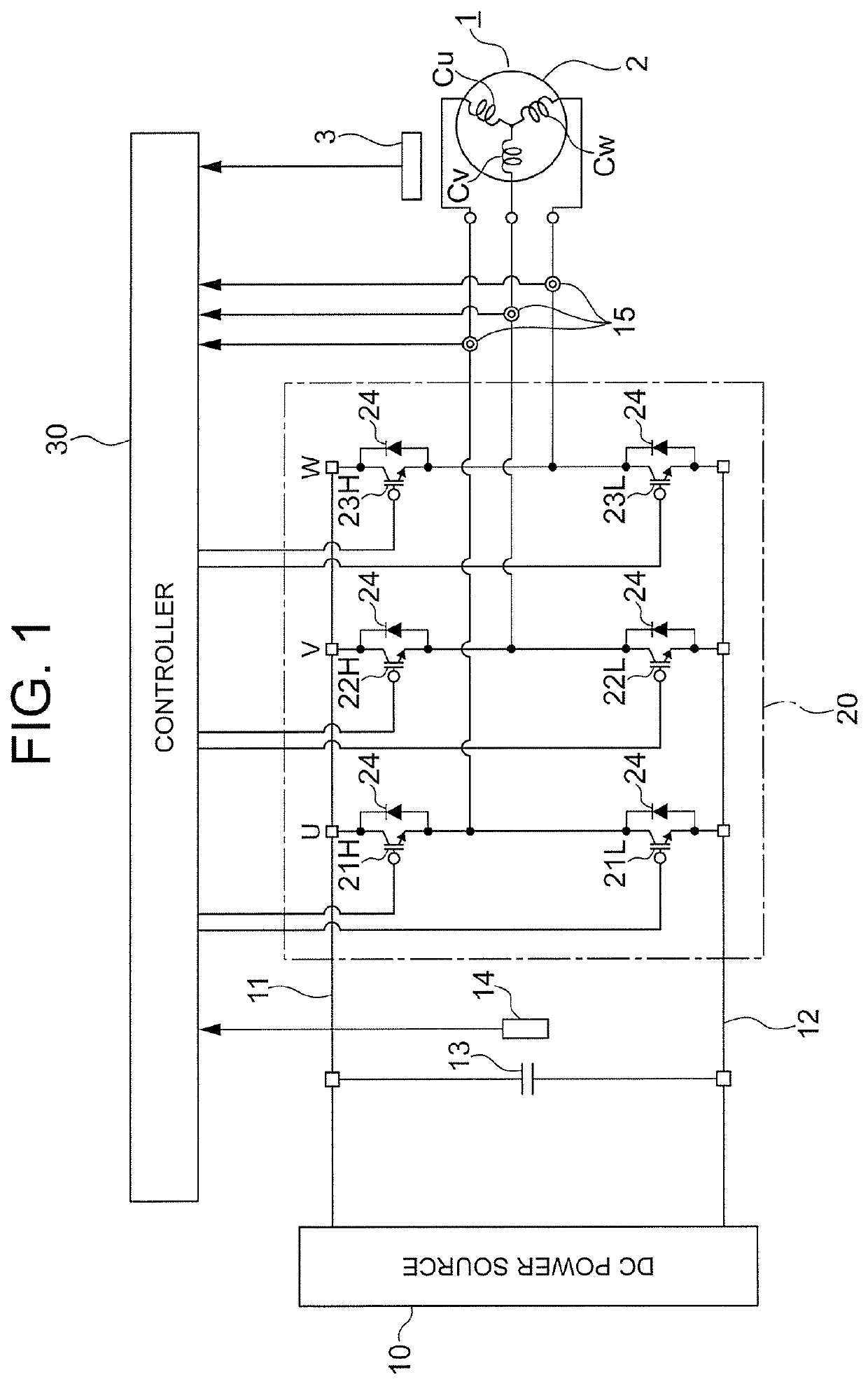
[0016]FIG. 1 is a schematic circuit diagram of an AC rotating electric machine and a controller therefor according to a first embodiment. An AC rotating electric machine 1 includes a stator, a rotor 2, and a magnetic-pole position sensor 3.

[0017]The stator includes windings of a plurality of phases. The stator in the first embodiment includes a U-phase winding Cu, a V-phase winding Cv, and a W-phase winding Cw. The U-phase winding Cu, the V-phase winding Cv, and the W-phase winding Cw are connected in a star or delta configuration. The rotor 2 rotates relative to the stator. Further, the rotor 2 includes a plurality of permanent magnets (not shown). The AC rotating electric machine 1 in the first embodiment is a permanent-magnet synchronous rotating electric machine.

[0018]The magnetic-pole position sensor 3 outputs an electric signal in accordance with a rotation angle of the rotor 2. For example, as the magnetic-pole position sensor 3, a Hall element, an encoder, or...


PUM


Abstract

In a controller for an AC rotating electric machine, a failure-state determining circuitry determines a failure state of a magnetic-pole position sensor based on an output signal from the magnetic-pole position sensor. A modulation-ratio switching circuitry outputs a target value of a modulation ratio and also changes the target value to be output based on a result of the failure-state determining circuitry. The modulation-ratio switching circuitry sets, when the magnetic-pole position sensor is determined as being abnormal by the failure-state determining circuitry, the target value to be smaller than in a case in which the magnetic-pole sensor is determined as being normal by the failure-state determining circuitry.

Description

BACKGROUND OF THE INVENTION1. Field of the Invention[0001]This disclosure relates to a controller for an AC rotating electric machine.2. Description of the Related Art[0002]In a related-art control mode switching device, the determination unit determines whether a sensor failure has occurred based on current command signals, current detection signals, and a velocity signal, and a switching unit. The switching unit switches a motor control mode from a vector control mode to a V / F control mode or a sensorless vector control mode in accordance with a sensor failure signal from the determination unit (see, for example, Japanese Patent Application Laid-Open H10-14300).[0003]Overmodulation control is known as a method of improving a voltage utilization rate of a power converter that drives an AC rotating electric machine. However, the control mode switching device described in Japanese Patent Application Laid-Open H10-14300 does not use a modulation ratio. Thus, when the overmodulation co...

Claims


Application Information

Patent Timeline
IPC IPC(8): H02K11/215H02K29/08H02P29/024H02P6/16
CPCH02K11/215H02K29/08H02P29/024H02P6/16H02P29/028H02P21/18H02P21/05H02P6/085H02P6/10H02P25/026H02P2207/05H02P2203/05H02P21/0021
Inventor HARADA, SHINGO
Owner MITSUBISHI ELECTRIC CORP
Why Eureka
Try Eureka