Pressure sensor
a technology of pressure sensor and sensor body, applied in the direction of fluid pressure measurement, fluid pressure measurement by electric/magnetic elements, instruments, etc., can solve the problems of sensor inability to meet the needs of the environment and non-negligible perturbations of the surrounding environmen
- Summary
- Abstract
- Description
- Claims
- Application Information
AI Technical Summary
Benefits of technology
Problems solved by technology
Method used
Image

Examples
first embodiment
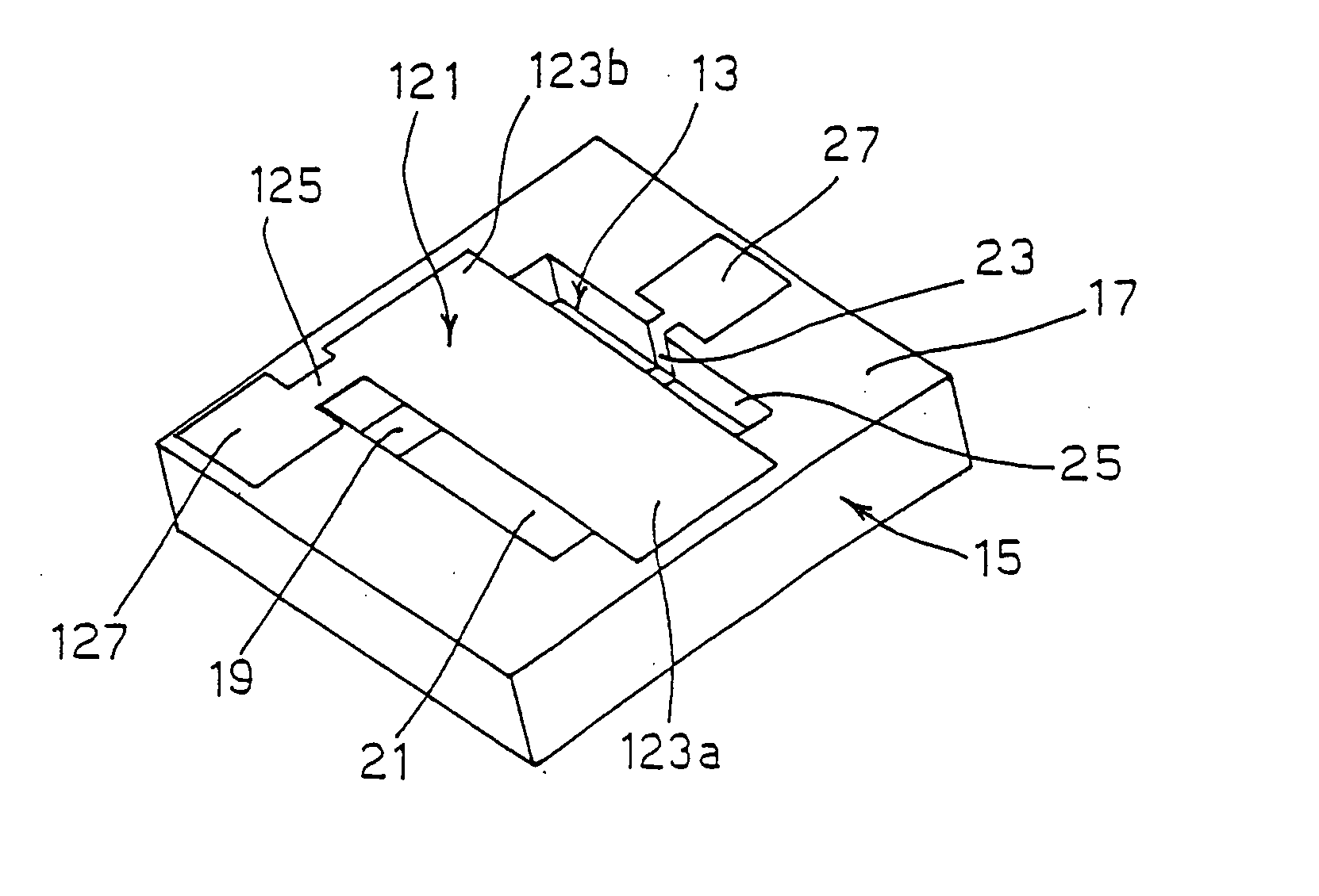
[0020] Referring to FIGS. 1a and 1b, there is shown the micro-electro-mechanical device of the pressure sensor according to the invention.
[0021] According to that embodiment, a vibrating planar resilient membrane 121 is suspended above a cavity 13 formed in a supporting base 15. The membrane 121 has a substantially rectangular shape and is fastened to peripheral rim 17 surrounding cavity 13 in supporting base 15 at two rectangular fastening regions 123a, 123b adjacent to the minor sides of membrane 121. The membrane is further provided with a side extension 125 partly overlapping peripheral rim 17 so as to define a corresponding contact area 127.
[0022] Supporting base 15 preferably is a silicon substrate or wafer on which cavity 13 has been formed by conventional etching techniques. A metal control electrode 21 is located inside cavity 13, in contact with bottom 19, and it is provided with a side extension 23 bent against side wall 25 of cavity 13. That extension partly covers peri...
second embodiment
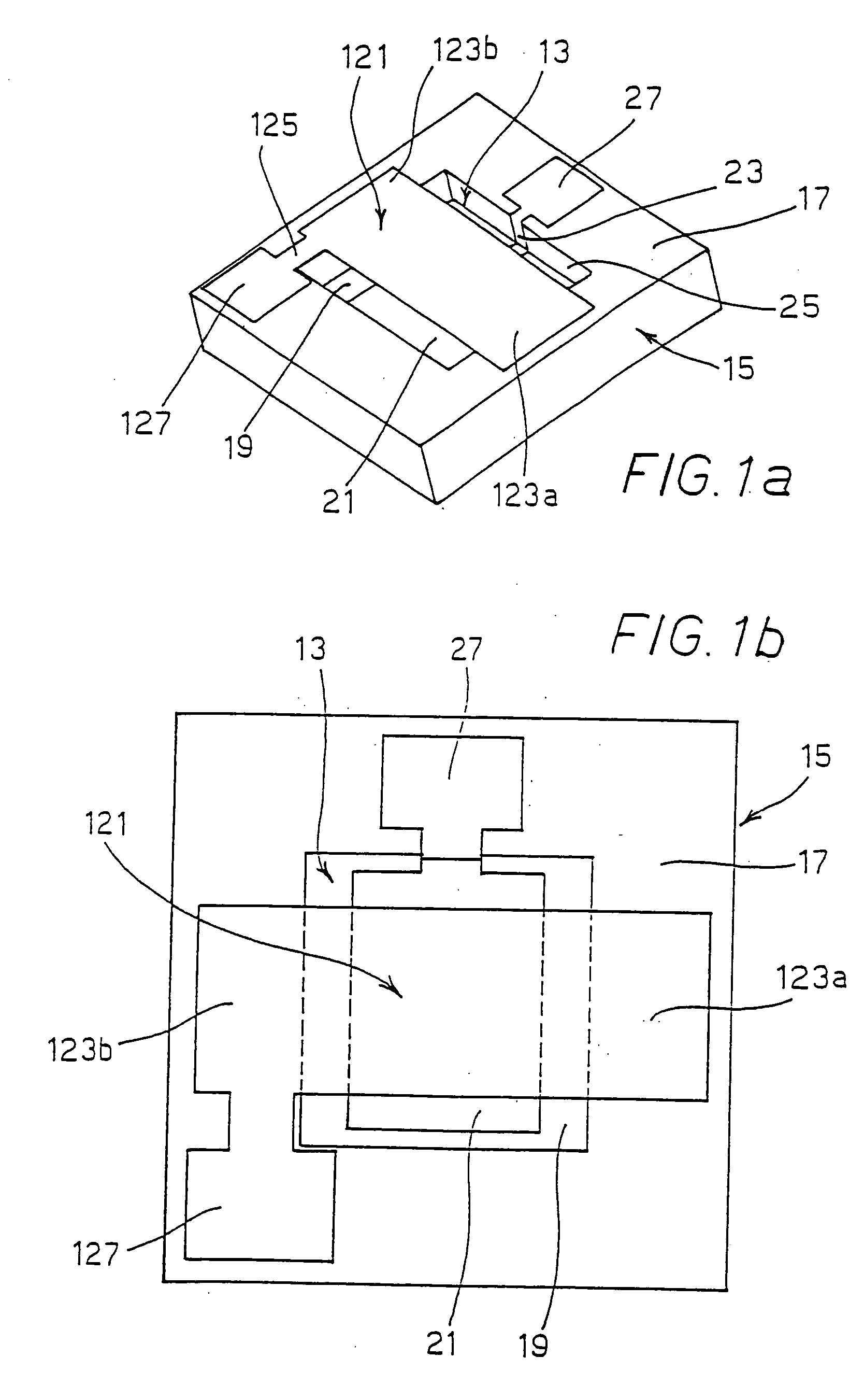
[0032] Referring to FIG. 2, where elements identical to those shown in FIGS. 1a and 1b have been omitted, the invention is shown in which the vibrating pumping stage is obtained by means of a planar, substantially H-shaped resilient membrane 221 comprising two parallel longitudinal beams 221a, 221b and a transversal central beam 221c. Similarly to the embodiment shown in FIGS. 1a and 1b, both parallel beams 221a, 221b are fastened at their respective ends 223a, 223b to peripheral rim 17 of supporting base 15. H-shaped membrane 221 is thus suspended above cavity 13 formed in supporting base 15.
[0033] Due to such a configuration, the H-shaped membrane may be imparted a torsional oscillation allowing attaining high resonance frequencies and great amplitudes. Actually, torsional resonance frequency is much higher than the flexion one. For instance, an aluminium membrane 150 μm long, 15 μm wide and 1.5 μm thick will have the following resonance frequencies: flexion 3.5e5 Hz, torsion 2.0e...
third embodiment
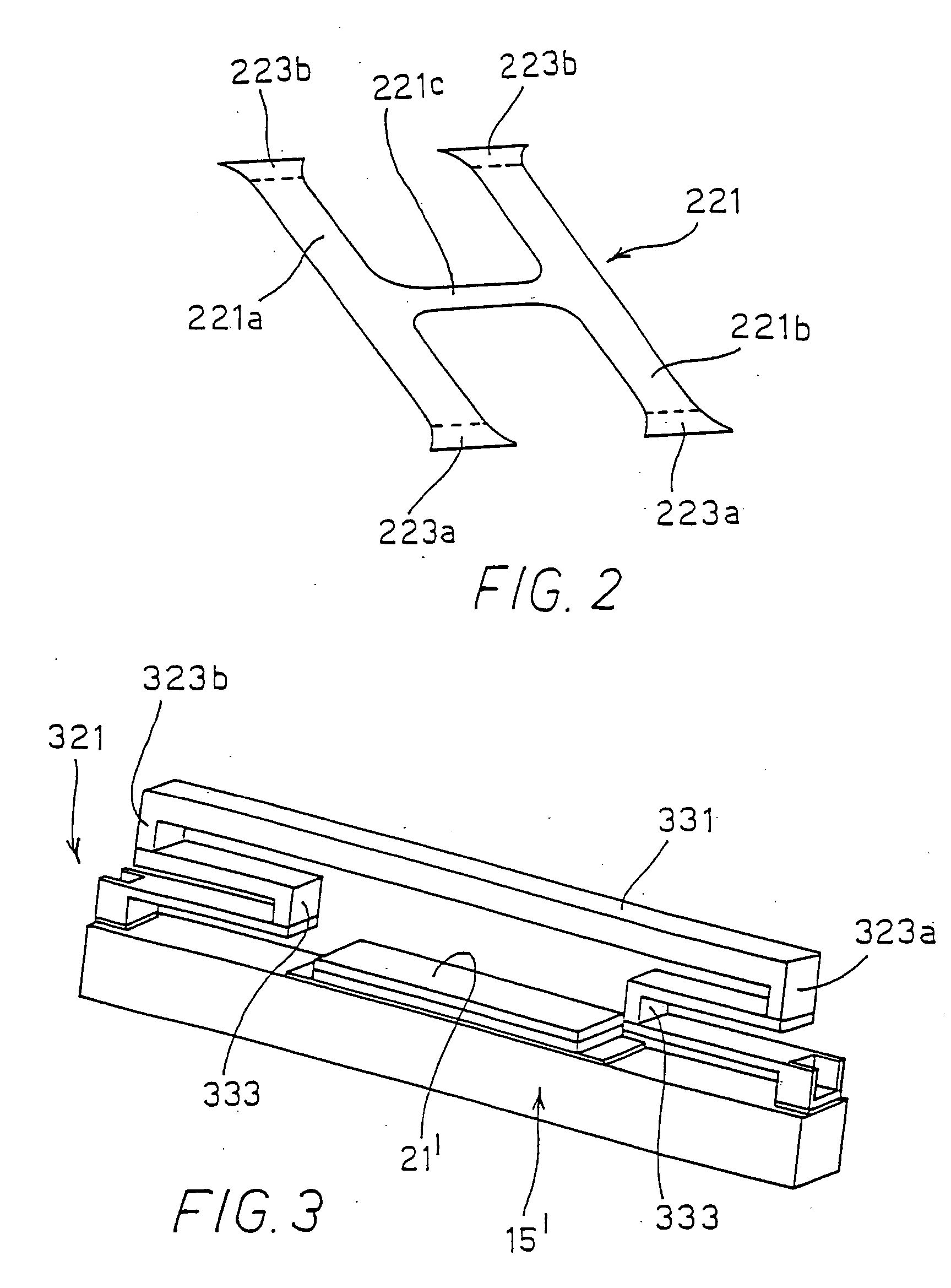
[0035] Turning now to FIG. 3, the invention is shown in which a multilayer vibrating assembly 321 is provided.
[0036] According to this embodiment, assembly 321 comprises a substantially rigid membrane 331 supported by substantially S-shaped resilient members or suspension springs 333, located under membrane 331 at respective opposed ends 323a, 323b thereof.
[0037] Resilient members 323a, 323b will be in turn fastened to a rectilinear supporting base 15′ onto which a control electrode 21′ is provided, in order to make assembly 321 vibrate due to the application of an electric field between said electrode 21′ and membrane 331.
PUM
 Abstract
Description
Claims
Application Information
 - R&D
- Intellectual Property
- Life Sciences
- Materials
- Tech Scout
- Unparalleled Data Quality
- Higher Quality Content
- 60% Fewer Hallucinations
Browse by: Latest US Patents, China's latest patents, Technical Efficacy Thesaurus, Application Domain, Technology Topic, Popular Technical Reports.
© 2025 PatSnap. All rights reserved.Legal|Privacy policy|Modern Slavery Act Transparency Statement|Sitemap|About US| Contact US: help@patsnap.com