Attenuating foam insert and method for manufacture

a technology of foam inserts and earpieces, which is applied in the direction of deaf-aid sets, earpiece/earphone attachments, electrical devices, etc., can solve the problems of increasing high frequency attenuation, exposing users to harmful noise, and virtually unavoidable acoustic leakage between flexible earseals and human heads, so as to improve overall attenuation

Inactive Publication Date: 2005-06-16
VAUDREY MICHAEL A +2
View PDF23 Cites 7 Cited by
  • Summary
  • Abstract
  • Description
  • Claims
  • Application Information

AI Technical Summary

Benefits of technology

[0016] What is needed is an acoustic foam insert that improves overall attenuation without interfering with the user, that can be shaped to conform to the three-dimensional contours of the earcup, and that can be manufactured in a repeatable manner.

Problems solved by technology

The acoustic leak that is formed between a flexible earseal and the human head is virtually unavoidable.
This gap allows ambient noise to enter the interior of the earcup and expose the user to harmful noise.
Increasing the mass of the earcup may increase the high frequency attenuation.
Both of these techniques lead toward more undesirable solutions in terms of comfort for the user.
Heavy earcups bolted to the head through an inflexible seal may be a theoretically ideal solution, but do not represent a practically realizable design.
However, the leak between either the seal and the earcup or the seal and the wearer's head is what most often controls the attenuation properties of the circumaural hearing protector.
Traditional foam insert design has been largely restricted to 2-dimensional die cut foam shapes because they are easy to manufacture.
However, nearly all earcups on the market are designed with three-dimensional curved interiors, into which 2-dimensional die cut shapes can never properly fit.
However, the Wilcox Patent does not point out the importance of the type of foam, the specific shape of the foam, the need to reduce the number of acoustic cavities and sharp angles, and the need to keep the external ear (pinna) free from contact.
However, the structural interaction between the walls and the leak between the seal and the head will likely limit the realizable attenuation at the ear canal.
The Gardner Patent does not teach the usage of foam for acoustic absorption inside an earcup.
Furthermore, no mention is made of specially designing acoustic absorption foam to improve hearing protection inside the earcup.

Method used


Image

  • Attenuating foam insert and method for manufacture
  • Attenuating foam insert and method for manufacture
  • Attenuating foam insert and method for manufacture

Examples


Embodiment Construction

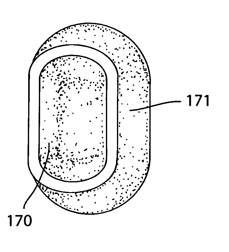
[0038] Embodiments of the present invention provide an acoustic foam insert that improves overall attenuation without interfering with the user, that can be shaped to conform to the three-dimensional contours of the earcup, and that can be manufactured simply and reliably.

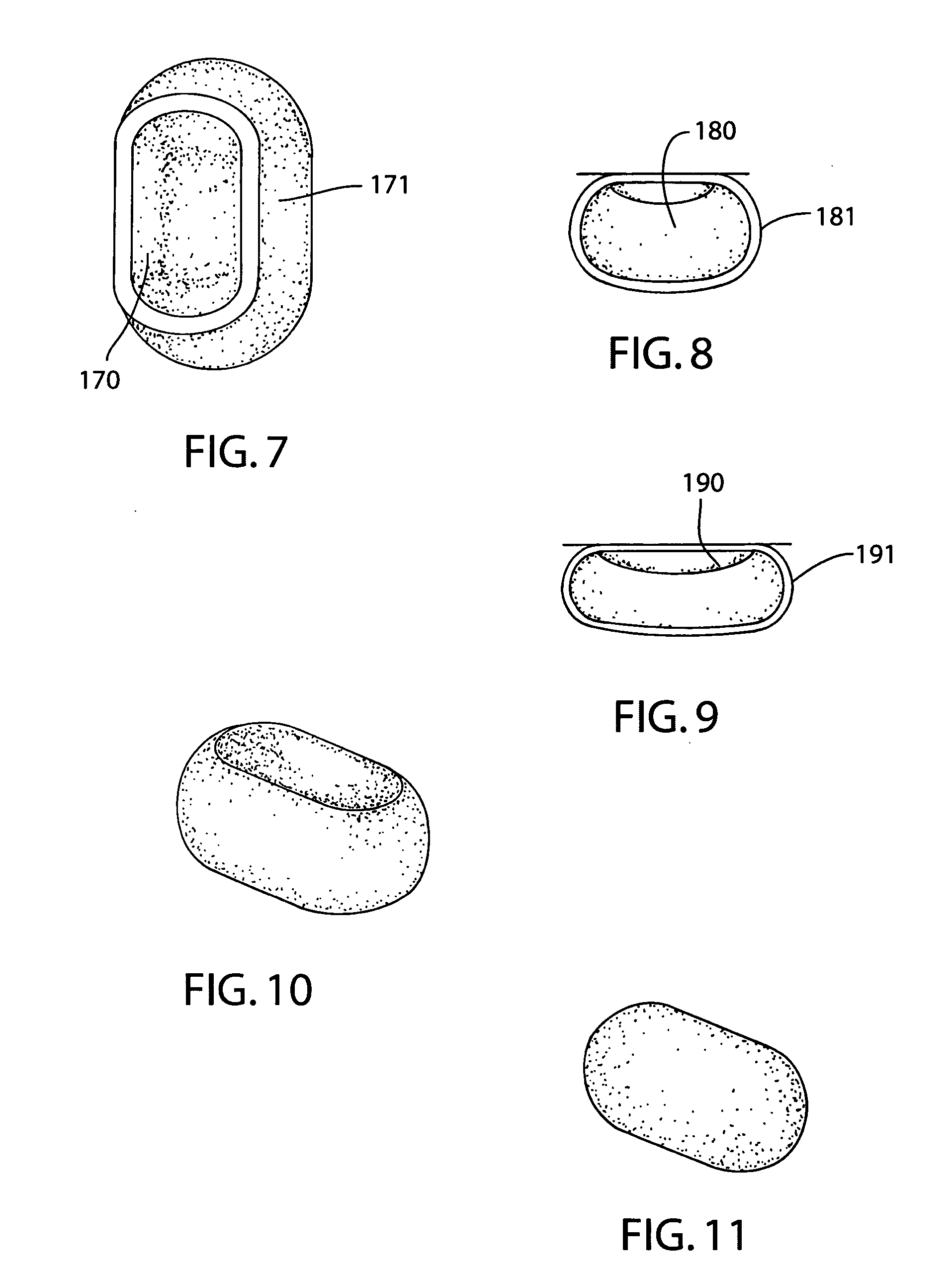
[0039]FIG. 7 illustrates an isometric view of an earcup 171 with the three-dimensional foam insert 170 inside. FIGS. 8 and 9 illustrate cross sectional views of the earcup 181, 191 with the new foam insert 180, 190 inside. The open cell foam is first cut to have the same exterior dimensions as the interior dimensions of the earcup. An isometric view of the foam is illustrated in FIG. 11. Because the foam is flexible, it can be compressed to fit through the hole in the earcup. Typically the hole to the interior of the earcup is smaller than the largest interior dimension of the earcup to result in a small projected surface area on the ear and a large cup interior volume.

[0040] The foam is first die cut from a sing...


PUM


Abstract

A shaped acoustic foam insert for use in improving the performance of circumaural hearing protectors is described. A foam block having a cross-section and shape is adapted to occupy the entire interior volume of an earcup of a circumaural hearing protector. The insert has no folds or open acoustic cavities. The surface of the insert that faces the ear of the user of the circumaural hearing protector comprises a curvilinear groove. The groove has no sharp angles and accommodates the average human pinna. A system and method of manufacturing the attenuating foam insert are provided.

Description

CROSS REFERENCE TO RELATED APPLICATIONS [0001] This application claims priority under 35 U.S.C. § 119(e) from provisional application No. 60 / 528,459 filed Dec. 10, 2003. The 60 / 528,459 application is incorporated by reference herein, in its entirety, for all purposes.BACKGROUND [0002] The present invention relates generally to hearing protection. More specifically, embodiments of the present invention provide a foam insert design, and method of manufacture for circumaural hearing protectors. [0003] Passive noise reducing circumaural hearing protectors are widely used in commercial, industry, and military applications where hearing protection from high level ambient noise is important. It is well known through past studies that the low-to-mid frequency noise attenuating properties of circumaural hearing protectors are generally controlled by the seal effectiveness and the vibration response of the earcup system. As a result, the majority of recent technology improvements have focused...

Claims


Application Information

Patent Timeline
Patent Type & Authority Applications(United States)
IPC IPC(8): H04R1/10H04R25/00
CPCA61F11/14
Inventor VAUDREY, MICHAEL A.DU, YUSAUNDERS, WILLIAM R.
Owner VAUDREY MICHAEL A
Why Eureka
Try Eureka