Disc brake comprising at least one inclinable brake pad

a technology of disc brake and inclination, which is applied in the direction of fluid actuated brakes, brake types, mechanical devices, etc., can solve the problems of affecting the stability of the vehicl

Inactive Publication Date: 2005-06-16
ROBERT BOSCH GMBH
View PDF13 Cites 13 Cited by
  • Summary
  • Abstract
  • Description
  • Claims
  • Application Information

AI Technical Summary

Benefits of technology

[0036] The present invention offers the advantage of making it possible to use small-size brake elements whose small size is compensated by the controlled wedging effect between the brake disk and the brake pad.

Problems solved by technology

Unfortunately there is a risk of that phenomenon causing the wheel to block, which is detrimental to the stability of the vehicle.

Method used


Image

  • Disc brake comprising at least one inclinable brake pad
  • Disc brake comprising at least one inclinable brake pad
  • Disc brake comprising at least one inclinable brake pad

Examples


second embodiment

[0135]FIG. 7 shows a second embodiment for which the amplifier means 22 also make it possible to improve the operating safety of an electrical brake device.

[0136] The device has a braking force generator GN formed, for example, by a motor M1 applying a braking force to the piston 13 during a braking stage in order to press at least one brake pad against the brake disk.

[0137] The amplifier means 22 are interposed between the piston and the pad.

[0138] The brake device also has additional application means 50 for pressing the brake pad against the disk in the event that the generator GN or M1 fails.

[0139] For example, the application means comprise resilient means, e.g. a spring disposed between the piston and a fixed element upstream from the piston along the axis X.

[0140] In the event that the motor M1 fails, the spring 50 is released and it presses at least one brake pad against the brake disk. The means 22, and in particular the motor M2 pivot the half-cylinders (or half-sphere...

fourth embodiment

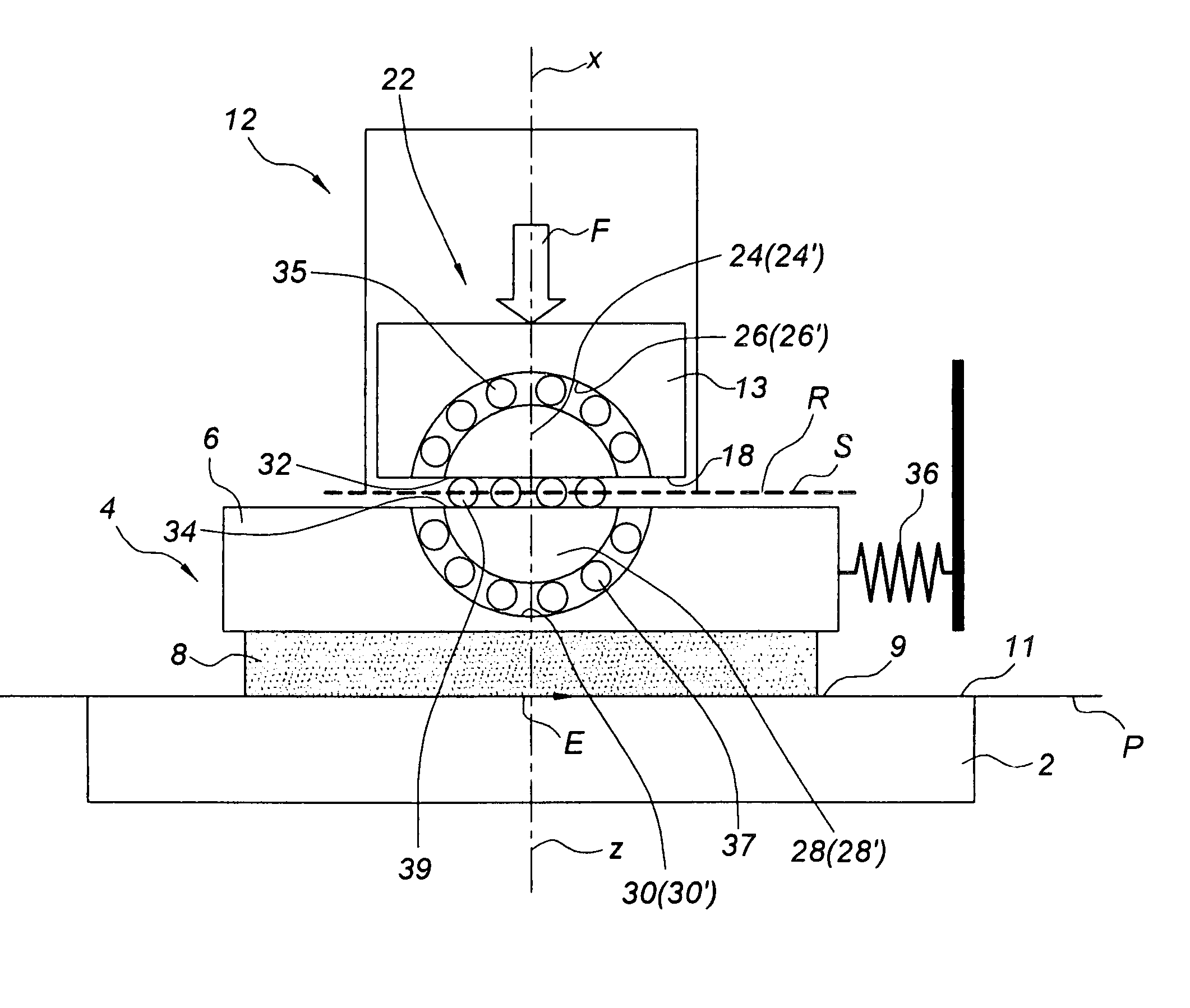
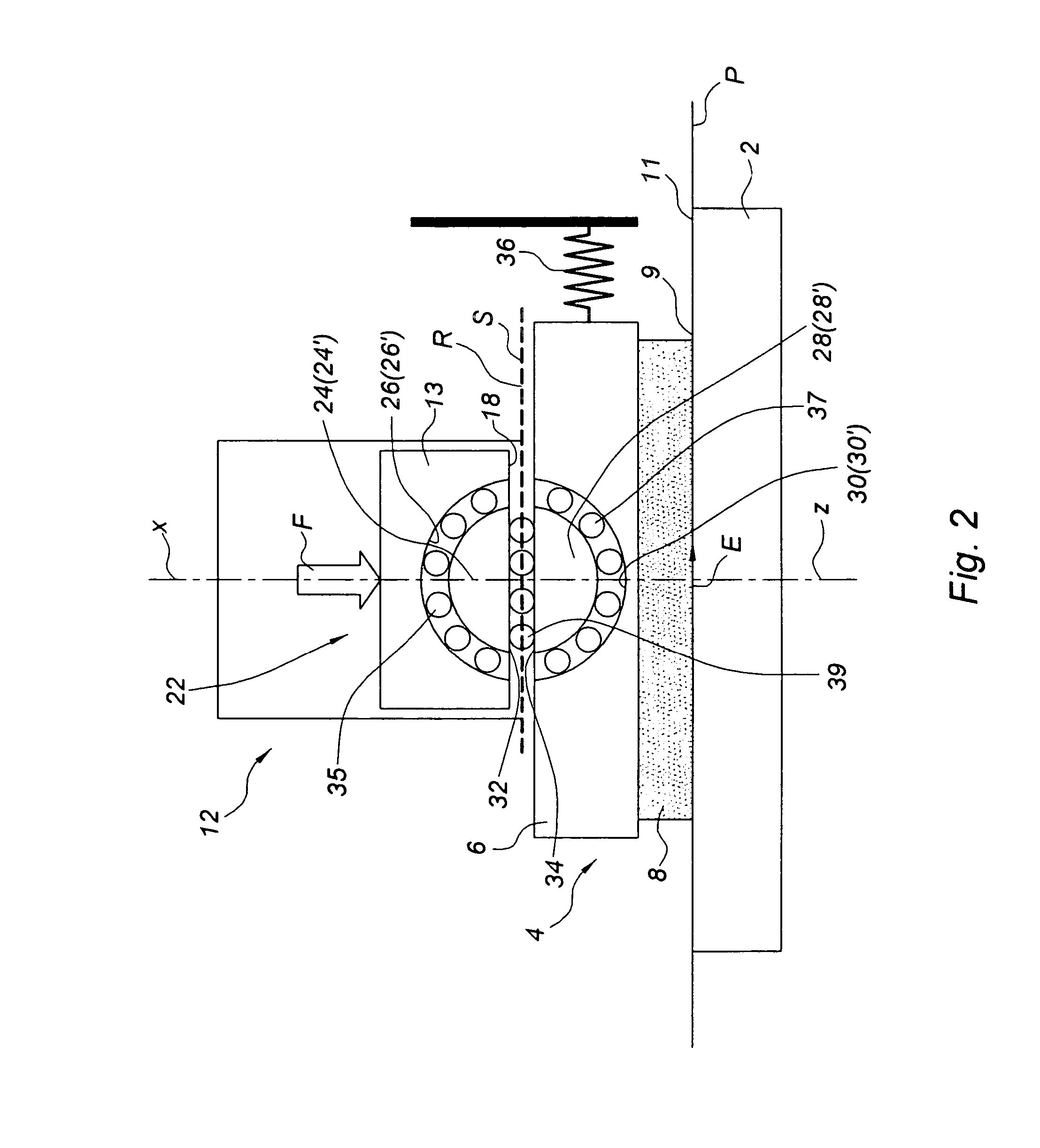
[0143]FIG. 8 shows a detail of the brake device of the present invention including means 22 forming the generator GN for generating a braking force EF and the amplifier for amplifying said braking force.

[0144] The first and second portions 24, 28 are of shapes making it possible, as they pivot, to bring the pad 4 towards the brake disk 2.

[0145] For example, the first and second half-cylinders (or the first and second half-spheres) form a cam of axis Y′ different from the axis Y and disposed in a recess of substantially circular section, the recess being formed by a first semi-cylindrical (or hemispherical) cavity carried by an element that is fixed relative to the brake pad and by a second semi-cylindrical (or hemispherical) cavity provided directly in the rigid support 6 of the pad or in an element secured to said pad, but nevertheless capable of being disunited from the pad while the brake pad is being changed.

[0146] It is also possible for the assembly formed by the first and t...


PUM


Abstract

The present invention mainly relates to a brake device for a motor vehicle, the brake device including a friction first element suitable for having a first face pressed against a first face of a second element which is secured to a wheel of the motor vehicle in order to slow said vehicle down, and an application third element for applying a braking force bearing via a first end against a second face of the friction first element that is opposite from the first face of the friction first element and suitable for pressing the friction first element against the second element, said brake device also including amplifier means for modifying the inclination of a tiltable plane containing the bearing surface between the friction first element and the application third element relative to a plane containing the first face of the second element.

Description

[0001] The present invention relates mainly to a brake device for a motor vehicle, and to a brake system including such a device. BACKGROUND OF THE INVENTION [0002] A known type of brake device for a motor vehicle has a friction element or “brake pad” suitable or being pressed under the action of a piston against a brake disk that is constrained to rotate with a wheel of the vehicle. [0003] The piston is in contact with a rear face of the brake pad in a plane that is substantially parallel to the plane of the brake disk. [0004] The piston is moved towards the brake disk, e.g. by means of a hydraulic fluid under pressure or by means of an electric motor. [0005] Document WO 98 / 14715 describes an electrical disk brake including an electric motor for moving a piston towards a brake pad and for pressing the brake pad against the brake disk when the brakes are applied. The bearing plane in which the piston bears against the brake pad forms a non-zero angle with the plane containing the br...

Claims


Application Information

Patent Timeline
Patent Type & Authority Applications(United States)
IPC IPC(8): F16D65/18F16D55/18F16D65/092F16D65/14
CPCF16D65/092F16D65/18F16D2127/10F16D2125/645F16D2121/24
Inventor BOISSEAU, JEAN-PIERRE
Owner ROBERT BOSCH GMBH
Why Eureka
Try Eureka