
Fail-safe electric actuator using high voltage capacitors

a capacitor and high-voltage technology, applied in the control circuit of a fail-safe actuator, multiple dynamo-motor starters, dynamo-electric converter control, etc., can solve the problem of no longer being deemed fail-safe, battery life is limited, actuators are no longer deemed fail-safe, etc., to achieve less expensive, increase energy storage, and reduce size

Active Publication Date: 2005-06-16
SIEMENS IND INC
View PDF10 Cites 26 Cited by
  • Summary
  • Abstract
  • Description
  • Claims
  • Application Information

AI Technical Summary

Benefits of technology

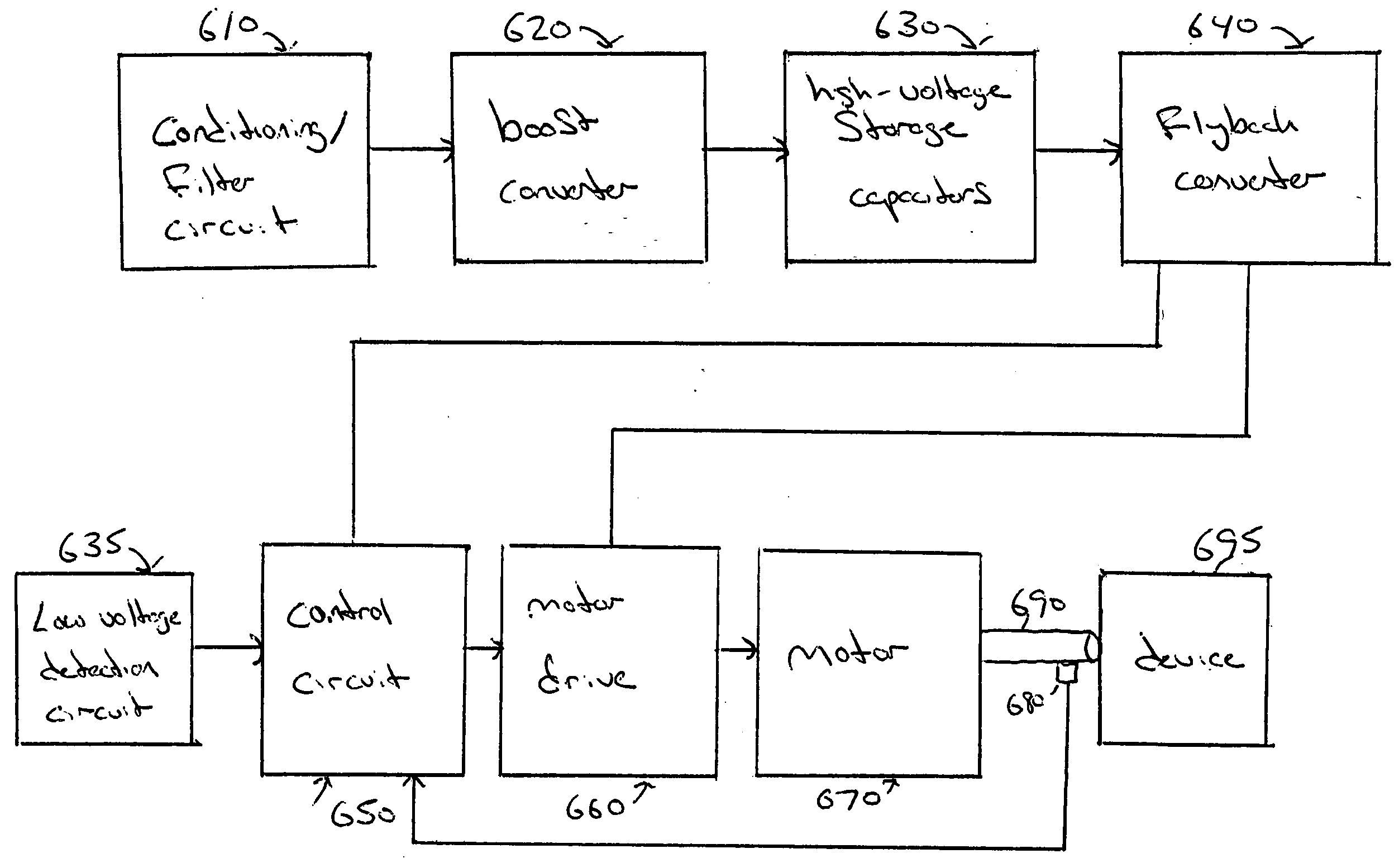
The present invention provides a fail-safe circuit for controlling a valve actuator that uses high voltage storage capacitors to charge at a high voltage and then convert back to a lower voltage to drive the motor of the actuator. This results in smaller, less expensive capacitors and increased energy storage. The fail-safe functionality is achieved by operating the motor from the high voltage capacitors.

Problems solved by technology

Mechanical spring solutions would provide open or closed positioning depending on the design, but would provide no capability for stopping at mid-position or field programmability.
If the battery was for some reason not functional, a signal would have to be sent to a control panel otherwise the actuator would no longer be deemed fail-safe.
In low current draw / standby applications, possibly operating at elevated temperatures, a battery has limited life.
The cost of the battery, and lower to replace it, makes the battery solution cost prohibitive.
The drawback would be the size and cost of a capacitor large enough to store the energy required to power the actuator in fail-safe circumstances.

Method used


Image

  • Fail-safe electric actuator using high voltage capacitors
  • Fail-safe electric actuator using high voltage capacitors
  • Fail-safe electric actuator using high voltage capacitors

Examples


Embodiment Construction

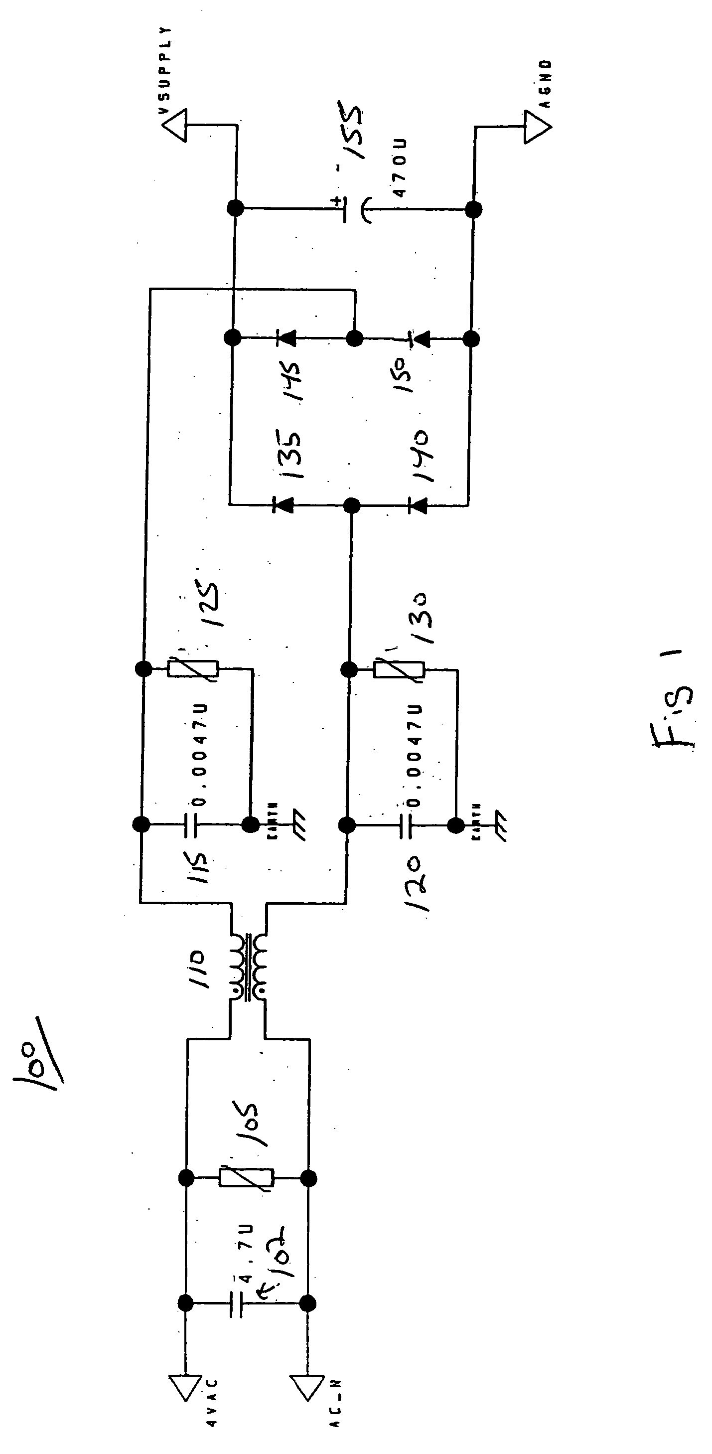
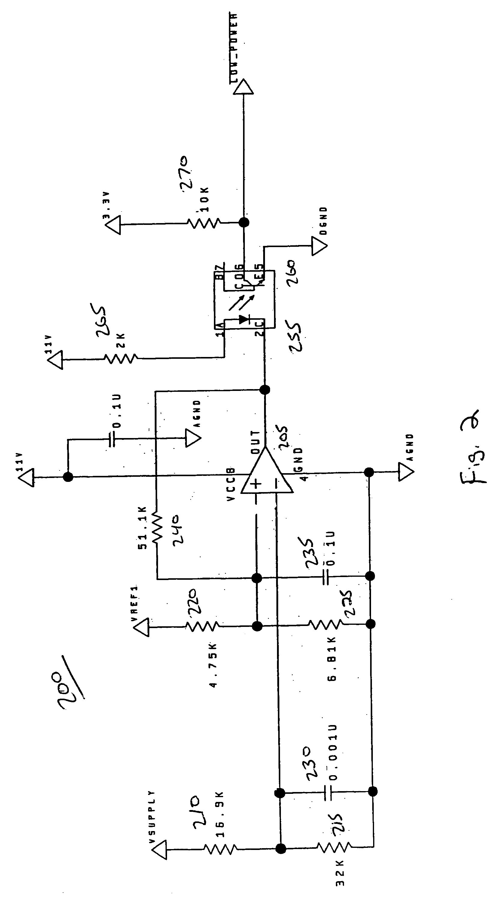
[0012]FIGS. 1-6 show an electric actuator return-to-normal failsafe system according to an embodiment of the present invention. The purpose of the fail-safe system is to provide a source of power and directional control which enables a motor discussed to be driven to a predetermined position when electric power is lost or removed so as to position a device such as an valve or a damper in a desirable position when power is lost. Turning now to FIG. 1, FIG. 1 is a conditioning circuit to convert an AC power source into a DC supply for a motor. The circuit 100 includes a capacitor 102 provided for EMI filtering to keep noise from affecting the 24V input voltage. In one embodiment, capacitor 102 is a 0.047 microfarad capacitor. Metal oxide varistor 105 is provided to reduce voltage surges into circuit 100. Choke 110 is provided as a common mode choke, and is provided as part of the filter network comprised of capacitors 115, 120 and metal oxide varistors 125, 130. Circuit 100 is further...


PUM


Abstract

According to the present invention, a fail-safe circuit for controlling an actuator is provided with an input voltage which is rectified and converted to a DC voltage. The DC voltage is boosted to a high level, and high voltage storage capacitors are charged at this high voltage level resulting in smaller, less expensive capacitors. The high voltage from the storage capacitors is then converted back to a smaller DC voltage to drive the motor of the actuator. Reduced size and increased energy storage is based on the relationship between capacitance and voltage in the equation: E=½CV2.

Description

[0001] This application claims the benefit of U.S. Provisional Patent Application Ser. No. 60 / 523,573 filed Nov. 20, 2003, which is incorporated herein by reference.FIELD OF THE INVENTION [0002] The present invention relates generally to heating, ventilation and air conditioning (HVAC) systems, and more particularly, to a control circuit for a fail-safe actuator provided with high voltage energy storage capacitors for positioning a valve using an actuator in the event of a power failure. BACKGROUND OF THE INVENTION [0003] HVAC systems for use in buildings incorporate electric actuators to control the position of devices such as dampers and valves. In certain applications it would be advantageous to position a valve, open, closed or mid-position by means of an independent actuator in the event of a power failure. This type of valve actuator would be termed fail-safe. Several methods could be used to store the energy required to position the valve in a desired position in the event of...

Claims


Application Information

Patent Timeline
Patent Type & Authority Applications(United States)
IPC IPC(8): H02M11/00H02P1/54
CPCH02M11/00
Inventor CHARLES, DONALD E.COOK, MATTHEW D.
Owner SIEMENS IND INC
Learn More