Automotive radar

a technology for autos and radars, applied in wave based measurement systems, instruments, reradiation, etc., can solve the problems of increasing unnecessary sidelobes, significant deterioration of azimuth accuracy, and wrong detection, and achieves a high level of azimuth accuracy. , the effect of easy production in light weigh

Inactive Publication Date: 2005-06-16
HITACHI LTD
View PDF7 Cites 24 Cited by
  • Summary
  • Abstract
  • Description
  • Claims
  • Application Information

AI Technical Summary

Benefits of technology

[0009] An object of the present invention is to obviate the problem noted above and to provide a low-cost, compact and light-weight automotive radar that excels in azimuth accuracy over a wide detectable range.
[0015] Also, by having the transmitting antenna protrude farther ahead than the receiving antennas, leaks from the transmitting antenna to the receiving antennas can be prevented, resulting in a further enhanced level of azimuth accuracy.

Problems solved by technology

However, a widen angle of the antenna beam inevitably brings an increase in unnecessary sidelobes (subbeams of weaker intensity radiating in different directions from the main beam).
The sidelobes cause leaks of unnecessary waves from the transmitting antenna to the receiving antennas, which would bring a deterioration in azimuth accuracy and an increase in wrong detections.
In the monopulse system, because the azimuth of the obstacle is determined according to the amplitude and phase of receive signals, the problem noted above leads to significant deterioration of the azimuth accuracy and wrong detection.

Method used


Image

  • Automotive radar
  • Automotive radar
  • Automotive radar

Examples


first embodiment

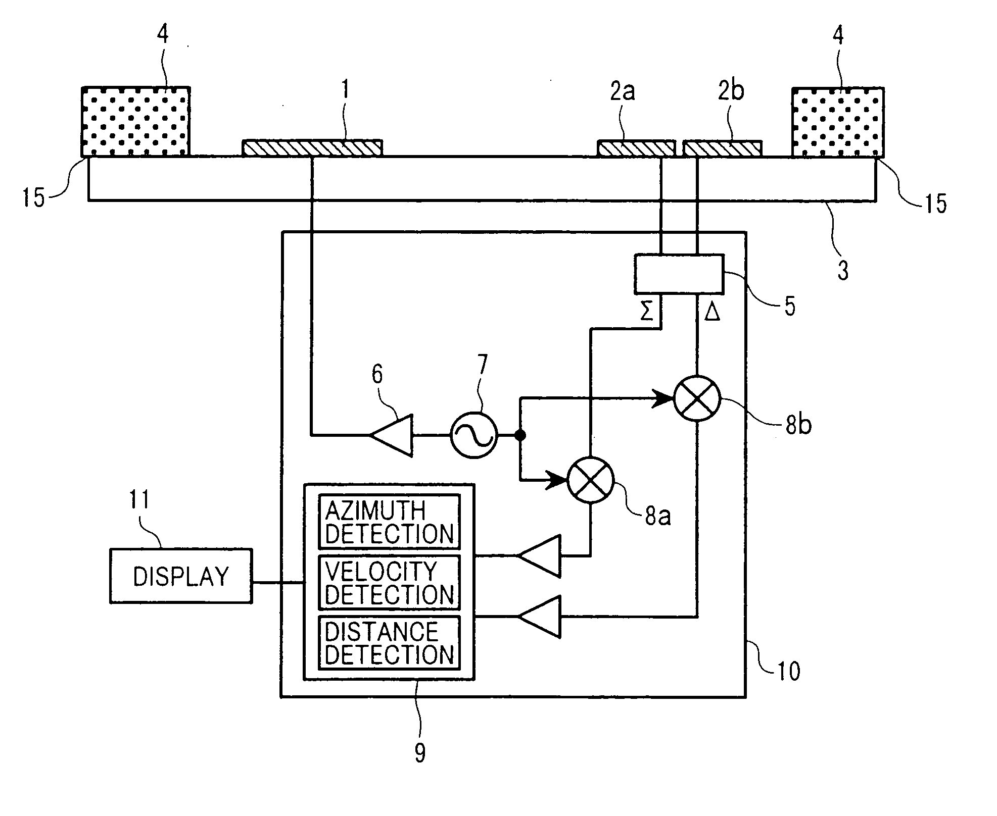
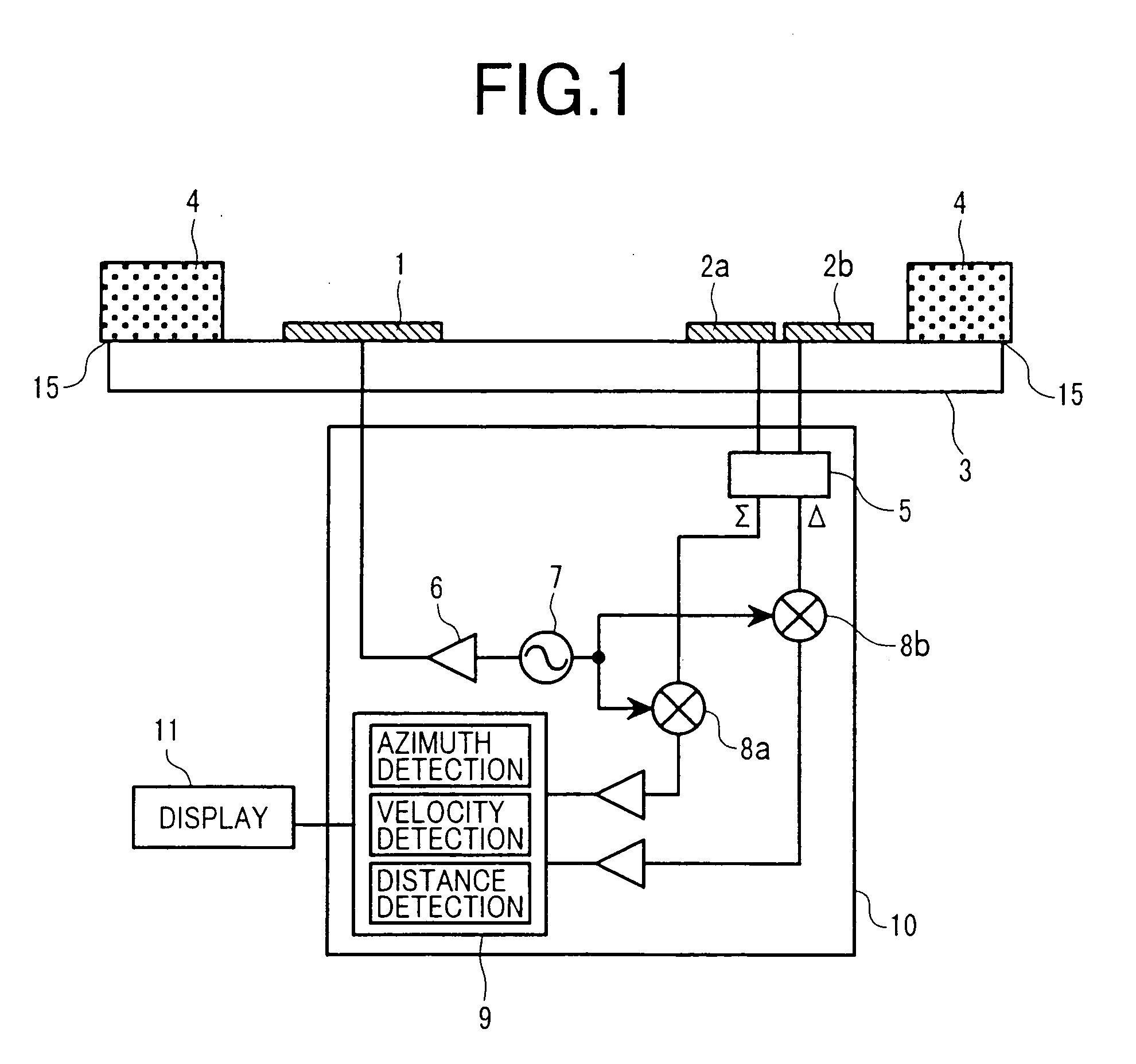
[0032]FIG. 2 shows a top view of the antennas used in the invention. A plurality of patch elements 12 and feeding lines 13 are configured over a dielectric substrate to constitute the transmitting array antenna 1 and the receiving array antennas 2a and 2b. Each of these array antennas is arranged on the antenna plate 3, and the radio wave absorbers 4 are arranged on the two sides of the edges 15 of the antenna plate 3.

[0033] In case of the absence of the radio wave absorbers 4, the reflected wave which has been Doppler-shifted by the obstacle and returned, would be diffracted by the edges 15 of the antenna plate 3 and become scattering unnecessary waves, part of which would come incident on the receiving array antennas 2a and 2b, but in this embodiment of the invention the reflected waves directed towards the edges 15 are absorbed by the radio wave absorbers 4 and thereby prevented from reaching the edges 15. Therefore, the generation of unnecessary waves by diffraction is prevented...

second embodiment

[0039] In this embodiment of the invention, as in the second embodiment, the whole edges of the antenna plate 3 are covered by the radio wave absorbers, and accordingly the absorption can be effective against diffracted waves not only in the lateral but also longitudinal direction of the drawing, with the result that wrong detection can be prevented and a high level of azimuth accuracy can be achieved.

[0040] Hereupon, the optimal positions and size of the radio wave absorbers 4 relative to the transmitting antenna 1 will be explained with reference to FIG. 5. The transmitting array antenna 1 and the radio wave absorbers 4 are arranged on the antenna plate 3, and a main beam mb having a radiation angle 2θ required for achieving a desired azimuth detecting performance is supplied from the transmitting array antenna 1. Then, assuming that the antenna 1 is thin enough, the optimal values of the height H of the radio wave absorbers 4 from the top face of the antenna 1 and of the distance...


PUM


Abstract

An automotive radar having a high level of azimuth accuracy and a broad detectable range by virtue of preventing leaks of unnecessary waves to receiving antennas is to be provided. A transmitting array antenna 1 and receiving array antennas 2a, 2b are arranged on an antenna plate (grounding conductor plate) 3 which serves to ground the antennas, and radio wave absorbers 4 are arranged on two sides of the edges 15 of the antenna plate 3. The radio wave absorbers 4 may be configured of, for instance, a sponge material containing radio wave absorbing grains.

Description

FIELD OF THE INVENTION [0001] The present invention relates to an automotive radar to be mounted on a mobile object, such as a wheeled vehicle, to detect the azimuth of an obstacle, its distance from the mobile object and relative speed. BACKGROUND OF THE INVENTION [0002] Automotive radars using millimeter waves are attracting interest as being most suitable for use in the prevention of car collisions and in following another vehicle as they are less susceptible to the interference of rain, fog, snow and other weather factors, dust and noise than ultrasonic radars and laser radars. Millimeter wave radars currently available in the market are mainly intended for use along expressways, and their detectable range and reach are approximately 16 degrees in azimuth angle and about 150 m in distance, respectively. [0003] Automotive radars are further expected to be applied in the near future to a more complex road environment, such as ordinary roads, and this would inevitably necessitate a...

Claims


Application Information

Patent Timeline
Patent Type & Authority Applications(United States)
IPC IPC(8): G01S7/03G01S13/42G01S13/44G01S13/931H01Q1/32H01Q1/42H01Q1/52
CPCH01Q1/3233H01Q1/525H01Q1/42H01Q1/3283G01S7/038G01S13/931G01S7/027
Inventor SHINODA, HIROSHIKONDOH, HIROSHIIZUMI, SHIHO
Owner HITACHI LTD
Why Eureka
Try Eureka